Category Archive Manuals

Bycassandre

dometic air conditioner manual

Dometic Air Conditioner Manual: A Comprehensive Guide

This guide provides essential information for Dometic AC units, covering installation, operation, maintenance, troubleshooting, and replacement options for various models.

Understanding Dometic Air Conditioner Models

Dometic offers a diverse range of air conditioning solutions tailored for recreational vehicles, trucks, and marine applications. Key distinctions lie in cooling capacity (measured in BTUs – British Thermal Units), with common sizes including 13.5K and 15K BTU models.

Furthermore, Dometic AC units are categorized by system type: ducted versus non-ducted. Ducted systems utilize existing RV ductwork for even air distribution, while non-ducted units deliver airflow directly from the unit itself. Models also vary based on control systems, ranging from traditional analog relay controls to more modern digital thermostats.

Recent redesigns focus on auxiliary cooling systems for the trucking market, emphasizing idle-reduction and fuel efficiency. Understanding these core differences is crucial for selecting the appropriate unit and utilizing the correct manual for your specific Dometic AC.

Identifying Your Specific Dometic AC Unit

Accurate identification is paramount for accessing the correct Dometic air conditioner manual and parts. Locate the unit’s model number, typically found on a sticker affixed to the AC housing – often on the side or underside; A common example is model 57915.531, a 13.5K BTU unit.

Note the manufacturing date, as designs and components can change over time. Determine if your system is ducted or non-ducted, and identify the control box type – specifically, whether it’s an older analog relay style or a newer digital model.

Knowing these details ensures compatibility when seeking replacement parts or troubleshooting issues, especially for older RVs like a 2002 U320 or a 2005 Forest River Wildwood.

Dometic AC Unit Installation

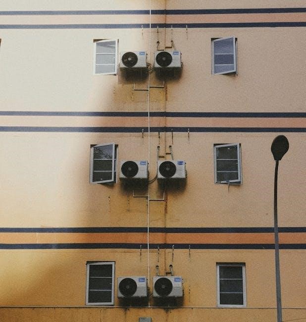
Proper installation is crucial for optimal performance and longevity of your Dometic AC unit. Rooftop installations require careful consideration of roof load capacity and existing penetrations. Ensure the mounting surface is structurally sound and sealed to prevent leaks.

Decide between ducted and non-ducted systems based on your RV’s existing setup. Ducted systems distribute air through vents, while non-ducted units provide localized cooling.

Electrical connections must adhere to safety standards, and compatibility with your RV’s power system is essential. Consult a qualified technician if you’re unsure about any aspect of the installation process.

Rooftop AC Installation Considerations

Rooftop installation demands meticulous planning. Assess your RV roof’s weight capacity before installing a Dometic AC unit, as exceeding the limit can compromise structural integrity. Existing roof penetrations should be thoroughly inspected for leaks and properly sealed.

Ensure adequate clearance around the unit for airflow and maintenance access. Consider the unit’s height to avoid obstructions like tree branches or low-hanging structures.

Properly securing the AC unit with appropriate mounting hardware is vital to withstand travel vibrations and wind loads. A professional installation guarantees safety and optimal performance.

Ducted vs. Non-Ducted Systems

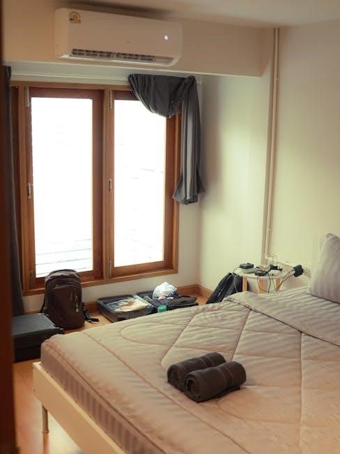
Dometic AC units come in ducted and non-ducted configurations, each offering distinct advantages. Ducted systems utilize existing RV ductwork to distribute cooled air evenly throughout the space, providing consistent temperatures and quieter operation.

Non-ducted units, often called “unit air conditioners,” deliver cool air directly into the immediate area, making them simpler to install and potentially more efficient for cooling a single zone.

Choosing between the two depends on your RV’s layout and cooling needs. Retrofitting a non-ducted system to ducted requires significant modifications.

Operating Your Dometic Air Conditioner

Proper operation ensures optimal performance and longevity of your Dometic AC unit. Begin by verifying the unit is receiving adequate power and the thermostat is set to your desired temperature. Familiarize yourself with the control panel, which governs fan speed, cooling mode, and potentially auxiliary heat functions.

Understanding the different cooling modes – Cool, Fan, and Auto – is crucial. “Cool” actively cools the air, “Fan” circulates air without cooling, and “Auto” adjusts operation based on the set temperature;

Control Panel Functions & Settings

The Dometic AC control panel is your central hub for managing climate control. Older models often feature analog relay-style controls, while newer units may have digital displays. Key functions include power on/off, temperature adjustment, fan speed selection (Low, Med, High, Auto), and mode selection (Cool, Fan, Auto, Heat – if equipped).

Pay attention to indicator lights, which signal operational status and potential issues. Some panels allow for zone control in ducted systems. Understanding these settings ensures comfortable and efficient operation, maximizing the benefits of your Dometic air conditioning system.

Understanding Cooling Modes (Cool, Fan, Auto)

Dometic AC units typically offer three primary cooling modes: Cool, Fan, and Auto. In ‘Cool’ mode, the compressor activates to actively lower the temperature, maintaining your desired setting. ‘Fan’ mode circulates air without cooling, useful for ventilation. ‘Auto’ mode intelligently adjusts cooling based on the set temperature and ambient conditions.

The ‘Auto’ setting often prioritizes energy efficiency. Selecting the appropriate mode optimizes performance and comfort. Consider using ‘Fan’ mode after cooling to prevent moisture buildup. Understanding these modes allows for tailored climate control within your RV or truck.

Dometic Air Conditioner Maintenance

Regular maintenance is crucial for optimal Dometic AC performance and longevity. This includes routine filter cleaning or replacement – typically every 30-90 days, depending on usage and environment – to ensure efficient airflow. Periodic coil cleaning is also essential, removing dust and debris that hinder cooling capacity.

A comprehensive inspection checklist should include verifying proper drainage, checking for loose connections, and listening for unusual noises. Proactive maintenance prevents costly repairs and extends the lifespan of your unit, ensuring consistent comfort during operation.

Filter Cleaning and Replacement

Maintaining clean filters is paramount for Dometic AC efficiency. Dirty filters restrict airflow, reducing cooling performance and potentially damaging the unit. Inspect filters monthly, or more frequently in dusty environments. Wash reusable filters with mild soap and water, ensuring they are completely dry before reinstalling.

Disposable filters should be replaced regularly – typically every 30 to 90 days. Always use the correct filter size and type specified for your Dometic model. A clean filter promotes optimal airflow, lowers energy consumption, and extends the life of your air conditioning system.

Coil Cleaning Procedures

Regularly cleaning both the evaporator and condenser coils is crucial for optimal Dometic AC performance. Dust and debris buildup reduces heat transfer efficiency. Before cleaning, always disconnect power to the unit! Use a soft brush or vacuum with a brush attachment to gently remove loose dirt.

For stubborn grime, a commercially available coil cleaner can be applied, following the manufacturer’s instructions carefully. Rinse thoroughly with water, avoiding electrical components. Clean coils improve cooling capacity, reduce energy consumption, and prevent potential system failures, ensuring long-lasting operation.

Regular Inspection Checklist

Proactive inspections extend your Dometic AC’s lifespan and maintain peak efficiency. Begin by visually checking for any physical damage to the unit’s housing and components; Confirm secure wiring connections and inspect the control box for corrosion.

Verify proper airflow by ensuring vents aren’t blocked. Regularly assess the condition of the filter – cleaning or replacing as needed. Listen for unusual noises during operation. Document any findings and address issues promptly to prevent minor problems from escalating into costly repairs. Consistent checks ensure reliable cooling.

Troubleshooting Common Dometic AC Issues

Addressing common problems promptly minimizes downtime and costly repairs. If the unit fails to power on, check the circuit breaker and power supply. Insufficient cooling often stems from a dirty air filter or blocked condenser coils. Unusual noises could indicate a failing blower motor or loose components.

For relay-style control boxes, inspect connections. If issues persist, consult the wiring diagrams. Remember safety first – disconnect power before any inspection. Document the problem and steps taken for efficient support requests. Prioritize simple solutions before considering complex repairs.

AC Unit Not Turning On

A Dometic AC unit failing to start requires systematic troubleshooting; First, verify the power source – check the circuit breaker in your RV’s electrical panel and ensure the AC unit is receiving voltage. Inspect the control box, particularly for older analog relay style systems, confirming secure connections.

Examine the thermostat settings; ensure it’s set to ‘Cool’ and a reasonable temperature. A blown fuse within the AC unit itself is another common culprit. If these steps fail, a professional diagnosis might be necessary, as internal component failure could be the cause.

Insufficient Cooling Performance

Reduced cooling capacity in your Dometic AC unit often stems from airflow restrictions. Begin by checking the air filter – a dirty filter significantly impedes airflow. Inspect the evaporator and condenser coils for accumulated dust and debris; cleaning these improves heat exchange efficiency.

Ensure proper ductwork sealing in ducted systems to prevent cool air leakage. Verify the unit’s BTU capacity is adequate for the RV’s size and insulation. Consider upgrading to a higher BTU model (like 15K) if needed, especially in warmer climates. A failing capacitor can also cause reduced performance.

Unusual Noises During Operation

Strange sounds from your Dometic AC unit require immediate attention. Rattling noises often indicate loose screws or debris within the unit or ductwork – a thorough inspection is crucial. A squealing sound could signal a failing blower motor or capacitor, demanding professional evaluation.

Humming might point to electrical issues, while clicking sounds could indicate a relay problem within the control box (especially analog relay style units); Never ignore persistent or escalating noises; they often precede complete system failure. Disconnect power before investigating internally.

Dometic AC Replacement Options

When your Dometic AC unit reaches its end of life, several replacement paths exist. Upgrading to newer BTU models, like 13.5K or 15K, can significantly improve cooling capacity, especially in older RVs. However, ensure compatibility with your existing 2002 or 2005 RV electrical system and ductwork.

Consider the control box type; newer ACs may require a digital thermostat instead of the original analog relay style. Carefully assess your RV’s roof structure to accommodate the new unit’s dimensions and weight. Professional installation is highly recommended for optimal performance and safety.

Upgrading to Newer BTU Models (13.5K, 15K)

Increasing BTU capacity offers enhanced cooling, particularly beneficial for older RVs or hotter climates. A jump from 13.5K to 15K BTU can noticeably improve comfort, but requires verifying your RV’s electrical system can handle the increased power draw.

For Forest River Wildwood models like the 37BHSS, assess the existing wiring and breaker size. Upgrading may necessitate a new breaker and potentially heavier gauge wiring. Ensure the roof structure can support the weight of a potentially larger unit. Consider professional installation to guarantee a safe and efficient upgrade.

Compatibility with Older RV Systems

Older RVs, like a 2002 U320, often utilize analog relay style control boxes, presenting compatibility challenges when upgrading AC units. Direct replacements might be limited, requiring adapters or complete control system overhauls.

Dometic offers solutions, but verifying compatibility is crucial. Consider if the new unit’s wiring and control signals align with the existing system. Replacing the entire control box alongside the AC unit simplifies installation and ensures full functionality. Consult with an RV technician to assess your specific setup and recommend the most suitable upgrade path, avoiding costly errors.

Dometic Air Conditioner Wiring Diagrams

Accessing accurate wiring diagrams is vital for safe and effective installation or repair of your Dometic AC unit. These diagrams detail the connections between the AC unit, the control box (especially important for older analog relay style systems), and the RV’s power supply.

Dometic provides wiring schematics in their official manuals and on their support website. Always disconnect power before working with wiring. Incorrect connections can cause damage or create a fire hazard. If you’re uncomfortable with electrical work, consult a qualified RV technician to ensure proper installation and operation.

Dometic AC Control Box Information (Analog Relay Style)

Older Dometic AC units often utilize an analog relay style control box. Understanding its function is crucial for troubleshooting. These boxes use mechanical relays to control the AC’s fan speeds, cooling modes, and overall operation, differing from modern digital control systems.

Common issues include relay failure or corrosion. Inspect the control box for burnt components or loose connections. Replacement parts are often available, but ensuring compatibility with your specific AC model is essential. Refer to wiring diagrams for correct connections, and always disconnect power before any inspection or repair work.

Dometic Truck HVAC Systems

Dometic offers specialized HVAC solutions designed for the demanding environment of commercial trucks. These systems prioritize driver comfort and fuel efficiency, often incorporating idle-reduction technology. Auxiliary air conditioning units allow drivers to rest comfortably without continuously running the truck’s engine, significantly reducing fuel consumption.

These systems can include rooftop units, bunk coolers, and integrated climate control systems. Installation requires professional expertise to ensure proper functionality and compliance with safety regulations. Dometic continually redesigns these products to meet the growing demand for efficient and reliable truck climate control.

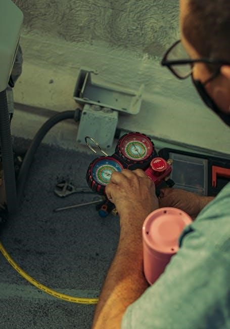
Fuel Economy & Auxiliary Cooling Systems

Dometic’s auxiliary cooling systems directly address fuel economy concerns for trucking fleets. By providing climate control without constant engine idling, significant fuel savings are achievable. Aerodynamic wheel covers, like those from Deflecktor, complement these systems, further enhancing fuel efficiency through reduced drag.

These auxiliary units allow drivers to maintain comfortable cabin temperatures during rest periods, eliminating the need to run the main engine for air conditioning. This translates to lower operating costs and a reduced carbon footprint. Investing in these technologies offers a strong return on investment for long-haul operations.

Finding Dometic AC Parts & Support

Locating Dometic AC parts and reliable support is crucial for maintaining your unit. Online retailers specializing in RV and truck accessories often stock a wide range of Dometic components, including filters, fan motors, and control boards. The Forest River Forums demonstrate a community actively discussing replacement options and troubleshooting.

Dometic’s official website provides access to detailed manuals, warranty information, and a network of authorized service centers. For older models, like the Dometic 57915.531, compatibility information is vital when sourcing replacements. Don’t hesitate to utilize online forums for peer-to-peer assistance and advice.

Dometic Air Conditioner Warranty Information

Understanding your Dometic AC unit’s warranty is essential for protecting your investment. Warranty coverage typically varies based on the model and purchase date, so retaining proof of purchase is vital. Dometic’s official website provides detailed warranty documentation and claim procedures.

Generally, warranties cover defects in materials and workmanship for a specified period. However, they often exclude damage resulting from improper installation, maintenance, or misuse. Review the specific terms and conditions associated with your unit to determine the extent of coverage. Utilizing authorized service centers ensures warranty validity.

Safety Precautions When Working with Dometic AC Units

Prioritizing safety is paramount when installing, maintaining, or repairing your Dometic air conditioner. Always disconnect the power supply at the breaker panel before commencing any work to prevent electrical shock. Wear appropriate personal protective equipment, including safety glasses and gloves.

Exercise caution when working on the roof, ensuring a secure ladder and stable footing. Be mindful of the unit’s weight and avoid dropping tools or components. If you are uncomfortable with any aspect of the work, consult a qualified technician. Improper handling can lead to injury or damage to the AC system.

Resources for Dometic AC Manuals & Documentation

Finding the correct documentation for your Dometic air conditioner is crucial for proper operation and maintenance. Dometic’s official website is the primary source for downloadable manuals, installation guides, and parts lists. Online RV forums, such as Forest River Forums, often host user-shared manuals and troubleshooting tips.

Additionally, many RV dealerships can provide access to Dometic documentation or assist in locating specific information. When searching, have your AC unit’s model number readily available (e.g., 57915.531). Utilizing these resources ensures you have the necessary information for safe and effective AC system management.

Bycassandre

irobot roomba 600 series manual

iRobot Roomba 600 Series Manual: A Comprehensive Guide

This detailed manual, sourced from manualsbase and manuals, offers extensive guidance for iRobot Roomba 600 Series owners, covering operation and maintenance effectively.

The iRobot Roomba 600 Series represents a foundational step into the world of robotic vacuuming, offering a convenient and automated cleaning solution for various floor types. This series, documented in user manuals available through resources like manualsbase and manuals, is designed for ease of use and reliable performance. It’s a popular choice for those new to robot vacuums, providing a balance between affordability and functionality.

These models are part of the broader iRobot collection, specifically categorized within manuals_contributions and additional_collections. The Roomba 600 Series excels at everyday dirt, dust, and debris removal, freeing up valuable time for users. Understanding its features, as detailed in the English language manual (item size 13.3M, added August 16, 2020), is key to maximizing its cleaning potential and ensuring long-term satisfaction. This introduction sets the stage for a comprehensive guide to operating and maintaining your Roomba 600.

Unboxing and Initial Setup

Upon receiving your iRobot Roomba 600 Series, carefully unpack the box to ensure all components are present, as outlined in the user manual sourced from manualsbase and manuals. The initial setup is straightforward, designed for a quick and hassle-free experience. Begin by identifying all included parts – the Roomba itself, the charging base, a power adapter, and potentially additional accessories like virtual wall beacons.

Before the first cleaning cycle, it’s crucial to properly position the charging base against a wall in an open area, ensuring sufficient space around it. Connect the power adapter and allow the Roomba to charge fully. Refer to the manual (added August 16, 2020) for specific charging times. This initial charge is vital for optimal performance and battery longevity. Once charged, you’re ready to begin exploring the Roomba’s cleaning capabilities!

What’s Included in the Box

The iRobot Roomba 600 Series package, detailed in manualsbase and manuals collections, typically contains several key components. You’ll find the Roomba 600 robot itself, designed for automated floor cleaning. A Home Base charging station is included, providing a convenient docking and recharging point for the robot. The power cord connects the Home Base to a standard electrical outlet, ensuring continuous operation.

Furthermore, the box includes a side brush for enhanced edge cleaning, reaching along walls and into corners. A dustbin is provided for collecting debris, and a filter helps trap fine particles. The user manual, added to the collection on 2020-08-16, offers comprehensive instructions. Depending on the specific model, you might also receive additional filter replacements or virtual wall barriers for customized cleaning zones.

Charging the Roomba 600

Properly charging your iRobot Roomba 600, as detailed in the manuals from manualsbase, is crucial for optimal performance. Begin by placing the Home Base against a wall on a level surface, ensuring ample space around it. Connect the power cord securely to both the Home Base and a functioning electrical outlet. Position the Roomba 600 onto the Home Base, aligning the charging contacts.

A solid light on the Home Base indicates a successful connection and charging process. Initial charging typically takes several hours – approximately 3 hours – to fully replenish the battery. The Roomba will automatically return to the Home Base to recharge when battery levels are low, or you can manually send it back. Regularly maintaining the charging contacts ensures efficient power transfer, extending battery life as outlined in the user manual added August 16, 2020.

Understanding Roomba 600 Components

Familiarizing yourself with the Roomba 600’s components, as detailed in the iRobot manual sourced from manualsbase, is essential for effective operation and maintenance. Key elements include the top cover, housing the power and clean buttons, and the bumper, designed to detect obstacles. Beneath the cover lies the dustbin, easily accessible for emptying, and the filter, vital for trapping debris.

The cleaning head module features both a bristle brush for agitation and an extracting brush to sweep dirt into the vacuum path. Side brushes extend cleaning reach along edges and corners. Understanding the function of each component, as outlined in the manuals, allows for targeted cleaning and efficient troubleshooting, ensuring your Roomba 600 delivers optimal cleaning performance, as per the collection manuals_contributions.

The Dustbin and Filter

The Roomba 600’s dustbin, detailed in the iRobot manual available on manualsbase, is a crucial component for collecting dirt and debris. Regular emptying – ideally after each cleaning cycle – maximizes suction power and cleaning efficiency. The dustbin is easily removable and designed for hygienic disposal of collected waste.

Equally important is the filter, which traps fine particles and allergens, ensuring cleaner air in your home. The manual emphasizes the need for periodic filter cleaning and eventual replacement (typically every two months, depending on usage) to maintain optimal performance. A clogged filter significantly reduces suction and can strain the motor. Following the guidelines in the manuals_contributions ensures a consistently clean and healthy environment.

Brushes: Bristle and Extracting

The iRobot Roomba 600 Series utilizes two primary brush types, as detailed in the user manual sourced from manualsbase. The bristle brush, a rotating multi-surface brush, agitates carpets and floors, loosening dirt and debris for effective collection. Simultaneously, the extracting brush – featuring rubber flaps – sweeps the loosened particles towards the vacuum’s suction path.

Regular inspection and cleaning of both brushes are vital, as hair, string, and fibers can become entangled, hindering performance. The manual provides clear instructions for brush removal and cleaning, emphasizing the importance of removing any obstructions. Maintaining clean brushes ensures optimal agitation and extraction, contributing to a thorough cleaning experience, as highlighted in manuals_contributions.

The Cleaning Head Module

The iRobot Roomba 600 Series’ cleaning head module, as described in the user manual available on manualsbase, is a crucial component for effective floor cleaning. This module houses both the bristle brush and the extracting brush, working in tandem to loosen and collect dirt, dust, and debris. It’s designed to adjust to different floor types, maintaining consistent contact for optimal performance.

The manual details how to remove and inspect the cleaning head module for any obstructions or damage. Proper maintenance, including cleaning the brush bearings and ensuring free rotation, is essential. A well-maintained cleaning head module guarantees efficient dirt removal and prevents motor strain, contributing to the Roomba’s longevity, as noted in manuals_contributions.

Operating Your Roomba 600

The iRobot Roomba 600 Series, as detailed in the user manual sourced from manualsbase, is designed for simple and intuitive operation. Powering on the device is typically achieved with a clearly marked “Clean” button, initiating an automatic cleaning cycle across your floors. The manual emphasizes understanding the Roomba’s behavior during operation, noting its navigation patterns and obstacle avoidance capabilities.

Users can leverage specific cleaning modes, like Spot Cleaning for concentrated areas or Edge Cleaning for along walls, enhancing cleaning precision. The manual provides guidance on interpreting the Roomba’s indicator lights, signaling status updates and potential issues. Familiarizing yourself with these operational aspects, as outlined in manuals_contributions, ensures optimal performance and a consistently clean home.

Powering On and Starting a Cleaning Cycle

Initiating a cleaning cycle with your iRobot Roomba 600 Series, as detailed in the manualsbase documentation, is remarkably straightforward. Locate the prominent “Clean” button on the top of the device – a single press activates the automated cleaning process. The Roomba will then begin navigating your floors, systematically cleaning as programmed.

Before starting, ensure the Roomba is not obstructed and has sufficient battery life. The user manual, found within the manuals collection, highlights the importance of a clear path for optimal performance. Observe the indicator lights; a solid green light confirms the cycle has begun. The Roomba will autonomously return to its Home Base when finished or low on power, as described in manuals_contributions.

Using the Clean Button

The “Clean” button on your iRobot Roomba 600 Series, as outlined in the comprehensive manualsbase guide, serves as the primary control for initiating and pausing cleaning cycles. A single, firm press activates the Roomba, sending it on its programmed cleaning route. Pressing the button again during operation immediately pauses the cleaning cycle, allowing for interruption if needed.

The manuals detail that a double-press of the Clean button will initiate the Docking function, instructing the Roomba to return to its Home Base for recharging. Understanding this functionality, sourced from manuals_contributions, is crucial for efficient operation. The button’s responsiveness is key; ensure a clear press for reliable activation, as noted in the collection of manuals.

Spot Cleaning Mode

The iRobot Roomba 600 Series’ Spot Cleaning Mode, detailed within the manualsbase documentation, is designed for concentrated cleaning of smaller, heavily soiled areas. To activate this mode, press and hold the “Clean” button for approximately three seconds, until a dedicated indicator light illuminates. The Roomba will then spiral outwards from its starting point, cleaning a roughly 3-foot diameter area with increased intensity.

Manuals_contributions emphasize that Spot Cleaning is ideal for spills or concentrated dirt patches. After approximately one minute, the Roomba will automatically return to its original starting location and cease operation. This focused cleaning approach, as described in the manuals, conserves battery life while effectively addressing localized messes, offering a targeted solution for quick cleanups.

Edge Cleaning Mode

The iRobot Roomba 600 Series’ Edge Cleaning Mode, as detailed in the manualsbase resources, is specifically engineered to clean along walls and around furniture. Initiated by pressing the “Clean” button twice rapidly, the Roomba will systematically follow the perimeter of the room, ensuring thorough cleaning in hard-to-reach areas.

According to manuals_contributions, the Roomba utilizes its side brush to effectively sweep debris from edges into its cleaning path. This mode is particularly useful for removing dust and dirt that accumulates along baseboards and furniture legs. The cleaning cycle continues until the Roomba completes a full perimeter sweep or until the battery is low. This focused approach, highlighted in the collection manuals, maximizes cleaning efficiency along edges.

Maintenance and Troubleshooting

Regular maintenance, as outlined in the iRobot Roomba 600 Series manual sourced from manualsbase, is crucial for optimal performance. This includes routinely emptying the dustbin, cleaning the brushes, and replacing the filter – typically every two months, depending on usage. Addressing common issues promptly extends the Roomba’s lifespan.

Manuals_contributions detail troubleshooting steps for scenarios like the Roomba not turning on (check power adapter and battery) or getting stuck (remove obstacles and ensure clear pathways). Poor cleaning performance often indicates a full dustbin or clogged brushes. The manuals emphasize the importance of inspecting and cleaning these components regularly. Following these guidelines, found within the collection manuals, ensures consistent and effective cleaning.

Emptying the Dustbin

The iRobot Roomba 600 Series manual, available through manualsbase, stresses the importance of frequent dustbin emptying for peak cleaning performance. A full dustbin significantly reduces suction power, impacting cleaning effectiveness. The process is straightforward: press the dustbin release button on the Roomba’s body. Carefully remove the dustbin and open it over a trash receptacle.

Manuals_contributions highlight the need to periodically clean the dustbin with a dry cloth to remove any lingering debris. Ensure the filter is also inspected during this process, as a clogged filter further diminishes suction. Regularly emptying the dustbin, as detailed in the collection manuals, maintains optimal cleaning capability and prolongs the Roomba’s operational life, preventing motor strain.

Cleaning the Brushes

The iRobot Roomba 600 Series manual, sourced from manualsbase, emphasizes regular brush cleaning for optimal performance. Hair, threads, and debris can easily become tangled around the bristle and extracting brushes, reducing their effectiveness. To clean, turn the Roomba over and remove the brush module. Carefully remove the brushes, noting their correct orientation for reinstallation.

Manuals_contributions suggest using the provided cleaning tool to remove wrapped hair and debris from both brushes. Inspect the brush caps for wear and tear, replacing them if necessary. A clean brush system ensures efficient dirt pickup and prevents motor strain. Consistent brush maintenance, as detailed in the collection manuals, maximizes cleaning power and extends the lifespan of your Roomba 600 Series.

Replacing the Filter

The iRobot Roomba 600 Series manual, available through manualsbase, highlights the importance of filter replacement for maintaining suction power and air quality. A clogged filter reduces cleaning effectiveness and can strain the vacuum motor. Manuals_contributions recommend replacing the filter every two months, or more frequently if you have pets or allergies.

To replace the filter, access the dustbin and remove the existing filter. Ensure the new filter is properly seated within the dustbin compartment. The collection manuals detail that using a genuine iRobot filter is crucial for optimal performance and to avoid damaging the Roomba. Regularly replacing the filter, as outlined in these resources, ensures consistent cleaning and a healthier home environment.

Troubleshooting Common Issues

The iRobot Roomba 600 Series manual, sourced from manualsbase, addresses frequent user concerns. If your Roomba won’t turn on, check the battery connection and ensure the charging base is properly plugged in. Getting stuck often indicates obstacles or tangled cords – clear the area before running a cleaning cycle. Poor cleaning performance usually stems from a full dustbin, clogged brushes, or a dirty filter; address these issues promptly.

Manuals_contributions suggest regularly inspecting the brushes for debris and cleaning them as needed. Refer to the detailed diagrams within the collection manuals for specific troubleshooting steps. Consistent maintenance, as detailed in these resources, will minimize issues and maximize your Roomba’s lifespan and cleaning efficiency.

Roomba Won’t Turn On

If your iRobot Roomba 600 Series fails to power on, the manual from manualsbase suggests several checks. First, verify the charging base is securely plugged into a working outlet. Next, ensure the Roomba is correctly positioned on the charging base, making good contact with the charging plates. A loose connection is a common culprit.

Consult the diagrams in the manuals_contributions collection to confirm proper docking. If the issue persists, inspect the battery compartment for any obstructions or damage. A depleted or faulty battery may require replacement. Remember to consult the full manual for detailed troubleshooting steps and safety precautions before attempting any repairs.

Roomba Gets Stuck

According to the iRobot Roomba 600 Series manual, frequently getting stuck indicates potential environmental factors. Review your room for loose cords, rug tassels, or low-hanging furniture that could impede Roomba’s movement. The manualsbase resource highlights the importance of a clear path for optimal performance.

Ensure Roomba isn’t attempting to navigate excessively thick carpets or transition between significantly different floor heights. Regularly check the Roomba’s brushes and wheels for tangled debris, as this can hinder its ability to move freely. The manuals_contributions collection provides diagrams illustrating common snag points. If Roomba consistently gets stuck in the same location, consider using Virtual Walls (if applicable) to restrict access.

Poor Cleaning Performance

If your iRobot Roomba 600 Series isn’t cleaning effectively, the manual suggests several checks. First, ensure the dustbin isn’t full, as a full bin drastically reduces suction power. Next, inspect the filter; a clogged filter significantly impacts cleaning ability and requires replacement. Refer to the manualsbase documentation for filter replacement intervals.

Examine the brushes – bristle and extracting brushes – for wear and tear or entanglement with hair and debris. Clean or replace them as needed. The manuals_contributions collection details brush maintenance procedures; Finally, verify the cleaning head module is free from obstructions. Consistent poor performance may indicate a need for a more thorough cleaning of Roomba’s internal components.

Advanced Features and Tips

The iRobot Roomba 600 Series, while straightforward, offers features to optimize cleaning. Scheduling cleaning cycles, though basic, allows for automated floor care – consult the manualsbase resources for programming instructions. Maximizing battery life involves regular charging and avoiding unnecessary operation on high-pile carpets, as detailed in the manuals.

If your model supports Virtual Walls (check your specific 600 Series variant), utilize them to restrict Roomba’s access to certain areas. Proper placement, as illustrated in the manuals_contributions section, is crucial for effectiveness. Regularly checking for software updates (if applicable) can also improve performance. Remember consistent maintenance, as outlined throughout this guide, is key to longevity.

Scheduling Cleaning Cycles

The Roomba 600 Series allows for convenient scheduling, automating your floor cleaning routine. While not as sophisticated as newer models, the scheduling function, detailed in the iRobot manuals sourced from manualsbase, enables pre-set cleaning times. Access the scheduling options through the Roomba’s control panel; the exact steps vary slightly depending on your specific 600 Series model.

Carefully program the desired start time and days of the week. Remember to ensure the Roomba is adequately charged and the cleaning path is clear before the scheduled cycle begins. Refer to the manuals_contributions section for troubleshooting scheduling issues. Consistent scheduling maximizes the benefit of automated cleaning, keeping your floors consistently tidy.

Maximizing Battery Life

To ensure optimal performance and longevity of your Roomba 600 Series battery, consult the comprehensive guides available on manualsbase. Regularly charging the Roomba, even when not in use, helps maintain battery health. Avoid frequent, short charging cycles; allowing a full charge is preferable. Minimize cleaning large areas on a single charge, as this strains the battery.

The iRobot manuals, found within the manuals_contributions collection, recommend replacing the battery every one to two years, depending on usage. Keeping the charging contacts clean also improves charging efficiency. Proper battery maintenance, as detailed in the user manual, significantly extends the Roomba’s operational lifespan and cleaning capabilities.

Using Virtual Walls (if applicable)

The iRobot Roomba 600 Series, depending on the specific model, may be compatible with Virtual Wall® accessories. These devices, detailed in the user manual sourced from manualsbase, create invisible barriers preventing Roomba from entering restricted areas. Proper placement is crucial; ensure the Virtual Wall is on a flat surface and directed towards the area you wish to block.

Refer to the manuals within the manuals_contributions collection for specific instructions on installing and operating Virtual Walls. Battery life within the Virtual Wall unit impacts its effectiveness, so regular battery checks are essential. Understanding the signal range and potential interference factors, as outlined in the iRobot documentation, optimizes the functionality of these helpful cleaning boundaries.

Bycassandre

orbit easy dial sprinkler timer manual

Orbit Easy Dial Sprinkler Timer Manual: A Comprehensive Guide

This manual provides detailed instructions for Orbit Easy Dial timers (96894‚ 96896‚ 96892). Learn setup‚ programming‚ troubleshooting‚ and safety information for optimal sprinkler system control;

The Orbit Easy Dial Timer represents a user-friendly approach to automated irrigation‚ designed for both indoor and outdoor applications. This timer simplifies lawn and garden watering schedules‚ offering convenience and water conservation. Models 96894‚ 96896‚ and 96892 share core functionality but may vary in station capacity.

Its intuitive “Easy-Set” logic allows for quick programming without complex setups. Users appreciate its reliability and the excellent customer service provided by Orbit. The swing door timer design offers easy access to controls‚ while features like Rain Delay enhance efficiency. This guide will walk you through installation‚ programming‚ and troubleshooting‚ ensuring optimal performance of your Orbit sprinkler system.

Understanding the Timer Models (96894‚ 96896‚ 96892)

Orbit offers several Easy Dial Timer models‚ primarily differing in the number of watering stations they support. The 96894 typically features three stations‚ suitable for smaller yards with distinct watering zones. The 96896 expands this to four stations‚ accommodating more complex irrigation needs. Model 96892 often represents a basic two-station option‚ ideal for simple setups.

Despite station count variations‚ all models utilize the same Easy-Set programming logic and share core features like Rain Delay and Manual Override. They all include wire access points at the bottom and require battery activation upon initial use. Choosing the right model depends on the size and zoning requirements of your landscape‚ ensuring efficient and targeted watering.

Key Features and Benefits

The Orbit Easy Dial Sprinkler Timer boasts user-friendly programming with its intuitive Easy-Set logic‚ simplifying schedule creation. A significant benefit is the Rain Delay function‚ conserving water by automatically pausing irrigation during rainfall. The Manual Watering mode provides instant control‚ bypassing programmed schedules for immediate watering needs.

These timers are designed for both indoor and outdoor use‚ offering installation flexibility. Customer reviews highlight excellent customer service and reliability. The swing door design protects the timer from the elements. Furthermore‚ the bypass mode allows continued operation even during power outages. Overall‚ the Easy Dial timer delivers convenience‚ water conservation‚ and dependable performance.

Initial Setup and Installation

Begin by carefully removing the timer from its packaging and inspecting for any damage. The timer features two holes at the bottom for wire access‚ facilitating installation. Before wiring‚ activate the pre-installed battery by removing the plastic strip. Ensure all wiring connections adhere to local and state electrical codes for safety and compliance.

Connect the sprinkler wires to the corresponding terminals‚ referencing the manual for correct placement. The timer can be mounted indoors or outdoors‚ providing installation versatility. Securely mount the timer to a wall or post‚ ensuring it’s protected from direct weather exposure. Proper installation is crucial for reliable operation and longevity.

Wire Connections and Terminal Locations

Proper wire connections are vital for correct sprinkler operation. Connect the remaining wires to their corresponding terminal locations‚ ensuring a secure fit. The timer utilizes specific terminals for each zone/station and the common wire. Refer to the wiring diagram within the manual for precise identification of each terminal.

Incorrect wiring can lead to malfunctioning sprinklers or timer damage. Double-check all connections before activating the system. Use appropriately sized wire connectors for a reliable and weatherproof seal. Ensure wires are firmly secured to prevent loosening due to vibrations or weather conditions. A secure connection guarantees optimal performance and prevents electrical hazards.

Battery Activation

The Orbit Easy Dial timer includes a pre-installed battery for backup and initial operation. To activate the battery‚ carefully remove the plastic strip located within the battery compartment. This strip prevents battery drain during storage and shipping. Removing it establishes the power connection‚ allowing the timer to display the time and retain programmed settings during power outages.

While the timer can operate solely on battery power‚ connecting it to a household power source is recommended for continuous operation and to recharge the battery. The battery serves as a reliable backup‚ preserving your schedule in case of a power interruption. Regularly check the battery level and replace it as needed to ensure uninterrupted performance.

Mounting the Timer (Indoor/Outdoor)

The Orbit Easy Dial timer is designed for both indoor and outdoor use‚ offering flexible installation options. The timer features two holes at the bottom specifically for wire access‚ simplifying mounting. For outdoor installation‚ choose a shaded location protected from direct sunlight and extreme weather to prolong the timer’s lifespan.

Securely mount the timer using screws (not included) through these holes onto a wall or flat surface. Ensure the mounting location is within reach of a power outlet if you intend to use the AC adapter. Indoor mounting provides additional protection from the elements. Regardless of location‚ ensure the swing door operates freely after mounting;

Programming the Timer with Easy-Set Logic

The Orbit Easy Dial timer utilizes an intuitive “Easy-Set” logic for simplified programming. Begin by setting the current time and date‚ crucial for accurate scheduling. Programming watering schedules involves defining “Stations‚” each controlling a specific zone or sprinkler group. You can customize start times‚ watering days‚ and durations for each station independently.

The timer allows for flexible scheduling‚ accommodating various landscape needs. Adjust watering duration to deliver the appropriate amount of water to each zone. Remember to consider factors like plant type‚ soil conditions‚ and seasonal changes when setting durations. The Easy-Set logic streamlines this process‚ making it user-friendly.

Setting the Current Time and Date

Accurate time and date settings are fundamental for proper timer operation. Upon initial setup‚ or after a power interruption‚ the current time must be programmed. Typically‚ this involves pressing and holding a “Set” or “Program” button‚ followed by using the dial to adjust the hour. Repeat this process for minutes‚ ensuring AM or PM is correctly selected.

Date setting usually follows a similar procedure – navigating through month‚ day‚ and year using the dial. Confirm each selection by pressing the “Set” button. Correct time and date ensure watering schedules activate at the intended times. Refer to your specific model’s diagram for button locations and detailed instructions.

Programming Watering Schedules (Stations)

The Orbit Easy Dial timer allows for multiple independent watering schedules‚ known as “stations;” To program a station‚ first select it using the dial. Then‚ enter the desired start time‚ utilizing the same “Set” and dial adjustment method as setting the time and date. Next‚ define the watering days – options typically include individual days of the week‚ or pre-set groupings like “Weekdays” or “Weekends.”

Each station can be customized to control different zones within your irrigation system. Ensure each station corresponds to a specific valve and sprinkler zone. Proper station programming optimizes water usage and caters to varying landscape needs.

Adjusting Watering Duration

Once a watering schedule (station) is selected‚ adjusting the duration is straightforward with the Orbit Easy Dial timer. After setting the start time and days‚ the display will prompt you to set the watering duration. Use the dial to increase or decrease the watering time‚ typically measured in minutes. The timer allows for precise control‚ often in one-minute increments.

Consider the specific needs of your plants and lawn when determining watering duration. Factors like soil type‚ plant species‚ and weather conditions influence optimal watering times. Regularly review and adjust durations to prevent over or under-watering‚ promoting healthy growth and conserving water.

Using the Manual Function

The Orbit Easy Dial timer offers a convenient manual watering mode for immediate irrigation needs. When the programmed schedule isn’t sufficient‚ or for one-time watering‚ this feature is invaluable. To activate manual mode‚ position the dial to “MANUAL.” The timer will then initiate watering on the currently selected station.

The duration of manual watering is typically pre-set or adjustable using the dial. Some models allow you to specify the watering time before activating manual mode‚ while others run for a default duration. Remember to return the dial to “AUTO” after manual watering to resume the programmed schedule. This ensures consistent‚ automated irrigation.

Activating Manual Watering Mode

To initiate manual watering with your Orbit Easy Dial timer‚ ensure the unit is in the “AUTO” position initially. Then‚ with the dial set to “AUTO”‚ firmly press and hold the “MANUAL” button. This action overrides the programmed schedule and activates watering on the currently selected station. The timer display will typically indicate “MANUAL” mode is active.

Some models may require rotating the dial directly to the “MANUAL” position. Refer to your specific model’s diagram for precise instructions. Once activated‚ the selected zone will water until manually stopped or a pre-set duration expires. Remember to return the dial to “AUTO” after use to resume scheduled watering.

Duration of Manual Watering

The duration of manual watering on your Orbit Easy Dial timer varies depending on the model and user settings. Typically‚ the timer will continue watering the selected station until you manually deactivate the “MANUAL” mode by either pressing the “MANUAL” button again or rotating the dial back to the “AUTO” position.

Some timers feature a pre-set maximum duration for manual watering‚ often around 24 hours‚ to prevent accidental prolonged operation. The remaining time in manual mode isn’t always displayed‚ so monitoring is recommended. Always check your specific model’s documentation for details regarding maximum manual watering times and deactivation procedures.

Advanced Features and Settings

The Orbit Easy Dial timer offers several advanced features beyond basic scheduling. The Rain Delay function temporarily suspends programmed watering schedules‚ conserving water during inclement weather. Users can set the delay duration‚ and the timer automatically resumes the regular schedule upon expiration.

Bypass Mode allows for immediate‚ unrestricted watering‚ overriding all programmed settings – useful for filling ponds or testing zones. Understanding these features enhances control and efficiency. Always consult the manual for specific instructions on activating and adjusting these settings‚ ensuring optimal performance and water conservation for your irrigation system.

Rain Delay Functionality

The Rain Delay feature is a crucial water-saving tool on your Orbit Easy Dial timer. When activated‚ it temporarily pauses your programmed watering schedule for a specified duration‚ preventing unnecessary irrigation during rainfall. Access this function via the timer’s control dial and buttons‚ as detailed in the user manual.

The remaining Rain Delay hours are clearly displayed on the timer’s screen. You can also return to the programmed schedule before the delay expires‚ offering flexibility. This feature is ideal for responding to unexpected weather changes‚ ensuring efficient water usage and promoting responsible lawn care. Proper use minimizes waste and optimizes your sprinkler system’s performance.

Rain Delay Duration and Resetting

The Orbit Easy Dial timer allows you to customize the Rain Delay duration to suit your local weather conditions. Typically‚ you can set the delay for periods ranging from hours to several days‚ providing ample control over your watering schedule. Consult your specific model’s manual for precise duration options.

Resetting the Rain Delay is straightforward. To cancel the delay and immediately resume your programmed schedule‚ navigate to the Rain Delay function within the timer’s menu and select the “Reset” or “Cancel” option. This will override the remaining delay time. Always verify the timer returns to automatic mode after resetting‚ ensuring consistent operation.

Bypass Mode Operation

The Bypass Mode on your Orbit Easy Dial timer offers a convenient way to temporarily disable automated watering without altering your programmed schedule. This feature is particularly useful for maintenance‚ landscaping‚ or when unexpected circumstances require immediate irrigation control. Activating Bypass Mode effectively puts the timer into a manual override state.

To engage Bypass Mode‚ typically you’ll need to locate and activate a dedicated bypass function‚ often indicated by an “RF SYNC ACTIVE BYPASS” setting or similar labeling. While in Bypass‚ the timer will ignore scheduled programs‚ allowing for on-demand watering. Remember to deactivate Bypass Mode to restore automated operation‚ ensuring your system functions as intended.

Troubleshooting Common Issues

Encountering problems with your Orbit Easy Dial timer? Several common issues can arise. If the timer isn’t displaying the correct time‚ check the battery and ensure proper initial setup; Sprinklers failing to activate could indicate wiring problems‚ a faulty valve‚ or an interrupted power supply – verify all connections.

Connectivity issues‚ if applicable to your model‚ might require resetting the timer or checking for interference. Review the wire connections and terminal locations carefully. If problems persist‚ consult the OrbitOnline resources for detailed troubleshooting guides and FAQs. Remember to always prioritize safety when inspecting electrical components.

Timer Not Displaying Correct Time

If your Orbit Easy Dial timer shows an incorrect time‚ the first step is to check the battery. A weak or depleted battery can cause inaccurate timekeeping. Ensure the battery is properly installed‚ and consider replacing it with a fresh one. After battery verification‚ re-enter the current time and date using the Easy-Set logic.

Double-check that you’ve selected the correct AM/PM setting. If the issue persists‚ try resetting the timer to its factory defaults (refer to the manual for reset instructions) and then re-programming the time. Confirm that there isn’t any electrical interference affecting the timer’s operation.

Sprinklers Not Activating

If your sprinklers aren’t activating with the Orbit Easy Dial timer‚ begin by verifying the power supply to the timer itself. Confirm the battery is fresh and correctly installed. Next‚ inspect the valve connections – ensure all wires are securely connected to the appropriate terminals‚ referencing the wiring diagram in the manual.

Check for any tripped circuit breakers or blown fuses in your electrical panel. Manually activate each station to isolate the problem; if only one station fails‚ the issue likely lies with that specific zone’s wiring or valve. If no stations work in manual mode‚ the timer may be faulty‚ or there could be a master valve issue.

Connectivity Problems (if applicable)

While the standard Orbit Easy Dial timer doesn’t inherently have “connectivity” issues like Wi-Fi models‚ problems can arise with the signal reaching the valve solenoids. Ensure proper wiring connections‚ as loose or corroded wires can disrupt the signal. Verify the solenoid wires haven’t been damaged by lawn equipment or weather exposure.

If using a wireless remote (on certain models)‚ check the remote’s battery and ensure it’s within range of the timer. Interference from other electronic devices could also be a factor. For timers with RF synchronization (like the ST2-RF)‚ confirm the sync button has been properly pressed to establish communication between the timer and remote. A weak signal can prevent activation.

Safety Precautions and Electrical Codes

Always disconnect power to the sprinkler system at the breaker box before installing or servicing the Orbit Easy Dial timer. Working with electrical wiring can be hazardous; if uncomfortable‚ consult a qualified electrician. Ensure the timer is properly grounded and protected from the elements‚ even if mounted outdoors.

Installation must adhere to all local and national electrical codes. The manual explicitly states compliance with Electrical Code and other state/local regulations is the installer’s responsibility. Use appropriately sized wiring for the voltage and amperage of the system. Avoid exposing the timer to standing water or excessive moisture. Regularly inspect wiring for damage and replace as needed to prevent shorts or fire hazards.

Customer Support and Resources (OrbitOnline)

For comprehensive support and additional resources‚ visit OrbitOnline. You can access the Easy-Set Swing Door Timer Manual directly on their website‚ providing a readily available digital copy. Many users praise Orbit’s excellent customer service‚ noting it surpasses support offered by other manufacturers.

Orbit provides a dedicated help desk‚ a significant advantage compared to companies lacking direct contact options. Customers consistently recommend the four-station timer for its ease of operation and reliability. If you encounter issues‚ OrbitOnline offers FAQs‚ troubleshooting guides‚ and contact information for direct assistance. Positive reviews highlight the responsiveness and helpfulness of their service department‚ ensuring a positive user experience.

Warranty Information

Orbit Irrigation Products warrants its Easy Dial Sprinkler Timers against defects in materials and workmanship for a specified period. While the exact duration varies by model (96894‚ 96896‚ 96892)‚ it typically covers one year from the date of purchase. This warranty applies to normal residential use and does not cover damage resulting from misuse‚ abuse‚ or failure to follow installation and operating instructions.

To obtain warranty service‚ proof of purchase is required. Contact Orbit Customer Support through OrbitOnline for assistance with warranty claims. The warranty does not cover labor costs or consequential damages. Adherence to local electrical codes is crucial for maintaining warranty validity. Refer to the complete warranty statement included with your timer or available online for detailed terms and conditions.

Bycassandre

manual label maker

Manual label makers offer a straightforward solution for organization, utilizing physical mechanisms to imprint text onto adhesive tapes.

These devices are gaining traction due to their simplicity and affordability, appealing to users seeking a tactile labeling experience.

Today is 03/16/2026 10:32:09 ()

What is a Manual Label Maker?

Manual label makers are self-contained devices designed to create adhesive labels without requiring batteries or a power outlet. They function through a mechanical process, often involving rotating wheels or levers with imprinted characters.

Users physically press or rotate these components to select letters and symbols, which are then transferred onto a tape via an embossing or printing mechanism.

These compact tools are ideal for quick, on-the-go labeling tasks, offering a tangible and reliable method for organization.

The Growing Popularity of Label Makers

Label makers are experiencing a resurgence in popularity, driven by a renewed focus on home organization and DIY projects. Their appeal lies in providing a customized and efficient labeling solution.

Many find them useful for school, office, and crafting needs, offering a tactile alternative to digital printing.

Compact and portable models, like the Nelko, further contribute to their growing demand, catering to users seeking convenience and versatility.

Types of Manual Label Makers

Manual label makers encompass handheld embossing models, traditional mechanical versions, and newer digital manual options offering expanded features like templates and connectivity.

Handheld Embossing Label Makers

Handheld embossing label makers create raised, textured labels by pressing letters and numbers onto a plastic tape. These are notably simple, requiring no batteries or electricity, making them exceptionally portable and reliable.

They are ideal for basic labeling needs, offering a classic, durable finish. While customization is limited to the available characters, their ease of use and affordability remain appealing.

Mechanical Label Makers

Mechanical label makers represent a traditional approach, employing a hand-crank or lever to physically imprint characters onto a tape. These devices are entirely self-contained, needing no power source, and are known for their robust construction and longevity.

They often feature a vintage aesthetic and are suitable for applications where a durable, non-digital labeling solution is preferred, offering a tactile and satisfying experience.

Digital Manual Label Makers

Digital manual label makers bridge the gap between traditional and fully electronic devices, offering features like multiple fonts, styles, and symbols via a small keyboard and display.

Models like those from Brother function similarly to typewriters, providing enhanced customization without requiring a computer connection. These often include Bluetooth connectivity and app integration for greater design flexibility, appealing to users desiring advanced features.

Key Features to Consider

When selecting a manual label maker, prioritize tape width, font options, and special characters. Portability and size are also crucial for convenient use.

Tape Width and Variety

Tape width significantly impacts label usability; options range from narrow bands for small items to wider tapes for larger surfaces. Epson label makers can print on tapes up to 0.71 inches (1.8 cm) wide.

Variety extends beyond width, encompassing materials like standard plastic, durable heat shrink tapes, and even magnetic decals for versatile applications. Consider your labeling needs when choosing tape types.

Font Styles and Sizes

Advanced manual label makers, like those from Brother, often feature diverse font styles and sizes, mimicking typewriter functionality. This customization allows for clear and visually appealing labels.

While simpler models may offer limited options, the ability to adjust font characteristics enhances readability and organization. Consider models with multiple fonts if varied aesthetics are desired for your labeling projects.

Special Characters and Symbols

Feature-rich manual label makers extend beyond basic lettering, incorporating a range of special characters and symbols for enhanced labeling.

These additions are useful for creating icons, warnings, or specific identifiers. The availability of emojis, for example, adds a playful touch to organization. Consider your labeling needs when evaluating a label maker’s symbol library.

Portability and Size

Manual label makers vary significantly in size and portability, impacting their usability in different scenarios. Newer models, like the Nelko P21, prioritize compactness—half the size of traditional devices—making them ideal for on-the-go organization.

Smaller, lightweight designs enhance convenience for school, office, or crafting applications, while larger models may offer more features but reduced portability.

Top Brands and Models

Leading brands include Brother, Epson, NIIMBOT, and Nelko, each offering diverse manual label maker models with varying features and price points.

Brother Label Makers

Brother offers a wide range of label makers, many featuring screens and keyboards, functioning similarly to typewriters.

These models are recommended for users desiring more features, including diverse fonts, colors, and even emojis.

Brother label makers provide extensive customization, allowing for detailed and personalized labels, though they generally represent a higher investment compared to simpler devices.

Epson Label Makers

Epson label makers are capable of printing on tapes 0.71 inches (1.8 cm) wide, offering over a hundred different tape types.

These include standard plastic, heat shrink tape, and even magnetic decals, providing versatile labeling options.

However, Epson’s average print speed is relatively slow at 0.24 inches (0.61 cm) per second, which may be a consideration for large-volume labeling projects.

NIIMBOT Label Makers

If the Nelko label printer appeals to you, but you desire more advanced customization, the NIIMBOT B1 Label Maker is a strong contender.

These devices offer increased functionality and control over label design, catering to users with specific labeling needs.

NIIMBOT models often feature app integration and multiple templates, enhancing the creative possibilities for various applications.

Nelko Label Makers

The Nelko Label Maker Machine with Tape, specifically the P21 Bluetooth model, presents a modern approach to labeling.

Compared to traditional label makers, Nelko devices boast a significantly reduced weight and size, enhancing portability and convenience.

This mini label maker is ideal for home, school, and office use, offering multiple templates for diverse labeling tasks.

Applications of Manual Label Makers

Manual label makers excel in home organization, school projects, crafting, and asset labeling, providing clear identification for various items and spaces.

Home Organization

Manual label makers are invaluable for decluttering and organizing homes. They efficiently label storage bins, pantry items, and spice racks, promoting a systematic approach to household management.

Teachers utilize them for classroom supplies, while parents identify children’s belongings, preventing mix-ups.

Personal item identification becomes effortless, and creating neat, labeled spaces is easily achievable with these convenient devices.

Office and School Use

Manual label makers streamline office tasks by organizing files, folders, and equipment. They’re perfect for creating clear, professional labels for binders, storage boxes, and supply cabinets, enhancing workplace efficiency.

In schools, teachers use them for labeling classroom materials, and students can identify their belongings.

These devices aid in creating organized learning environments and promoting responsibility.

Crafting and DIY Projects

Manual label makers unlock creative possibilities for crafters and DIY enthusiasts. They’re ideal for labeling handmade goods, organizing craft supplies, and adding personalized touches to gifts.

From scrapbooking and cardmaking to home décor projects, these tools offer a unique aesthetic.

Labels can identify materials, dates, or simply enhance the visual appeal of finished creations, adding a professional finish.

Asset and Inventory Labeling

Manual label makers provide a cost-effective solution for basic asset and inventory labeling needs. They’re suitable for small businesses or home workshops requiring simple identification of tools, equipment, or storage containers.

Creating durable labels helps track possessions and streamline organization.

While not ideal for large-scale operations, they offer a practical method for clear and consistent labeling, improving efficiency.

Comparing Manual vs. Digital Label Makers

Manual label makers generally cost less but offer fewer customization options compared to digital models. Digital versions provide greater flexibility and features.

Cost Comparison

Manual label makers typically represent a budget-friendly labeling solution, with simpler models available for under $30. More feature-rich manual options, like those resembling typewriters from brands like Brother, can reach higher price points.

Conversely, digital manual label makers, such as the Nelko P21 or NIIMBOT B1, fall into a mid-range cost bracket, often between $40 and $70, reflecting their added functionalities like Bluetooth connectivity and app integration.

Ease of Use

Manual label makers generally boast intuitive operation, requiring minimal technical expertise. Basic models involve simple hand-pressing mechanisms for character selection and imprinting, making them accessible to all ages.

Digital manual options, while offering more features, maintain user-friendliness through integrated screens and keyboards. However, mastering advanced functions like template selection or app connectivity may require a slight learning curve.

Customization Options

Manual label makers present varying degrees of customization. Simpler models offer limited font choices and character sets, focusing on basic labeling needs. More advanced devices, like those from Brother, expand options with diverse fonts, colors, and even emojis.

The availability of different tape types – plastic, heat shrink, magnetic – further enhances personalization. App integration, as seen in Nelko models, unlocks template access for tailored labels.

Using a Manual Label Maker: A Step-by-Step Guide

Begin by preparing your manual label maker and inserting a compatible tape cartridge. Then, create your desired label and carefully print it!

Preparing the Label Maker

First, ensure your manual label maker is clean and free of any debris that could hinder operation. Next, carefully open the tape compartment and insert a new, compatible tape cartridge, aligning it correctly according to the device’s instructions.

Confirm the tape feeds smoothly through the mechanism. Finally, if your model requires batteries, verify they are installed correctly or connect the power source for optimal performance before creating labels.

Creating and Printing Labels

Begin by composing your desired text using the label maker’s keys or dial. Select your preferred font style and size, if available, and any special characters or symbols needed for clarity.

Once satisfied with the preview, firmly press the print lever or button to imprint the text onto the tape. Carefully peel the newly printed label from its backing and apply it to the intended surface.

Troubleshooting Common Issues

If the label maker jams, gently open the tape compartment and carefully remove any tangled tape fragments. For faded prints, ensure sufficient battery power or replace them entirely. Uneven or misaligned labels often indicate improper tape loading – re-insert the tape cartridge correctly.

Should keys become unresponsive, try cleaning around them with a soft, dry cloth. Persistent issues may require consulting the device’s manual or contacting customer support.

Label Maker Tape Options

Various tape types enhance functionality, including standard plastic, heat shrink for wires, and magnetic tapes for flexible surfaces.

Epson offers over a hundred tape types!

Standard Plastic Tapes

Standard plastic tapes represent the most common and versatile option for manual label makers, suitable for a wide array of labeling needs.

These tapes are ideal for general home, office, and school applications, offering excellent adhesion to various surfaces.

They come in numerous colors and widths, providing flexibility in customization.

Epson provides a vast selection, exceeding one hundred different types, ensuring users can find the perfect tape for their specific requirements, from basic identification to decorative purposes.

Heat Shrink Tapes

Heat shrink tapes are a specialized option offered by brands like Epson, designed for labeling wires, cables, and other cylindrical objects.

When heated, these tapes conform tightly to the shape of the item, providing a durable and professional-looking label that resists peeling or damage.

This makes them invaluable for electrical work, organization, and identifying components.

They offer a secure and long-lasting labeling solution where standard tapes might fail.

Magnetic Tapes

Magnetic tapes represent another versatile labeling solution compatible with certain manual label makers, notably those from Epson, which boasts over a hundred tape types.

These tapes feature a magnetic backing, allowing them to adhere to metal surfaces like filing cabinets, refrigerators, and toolboxes.

They are easily repositionable and reusable, offering flexibility for dynamic labeling needs.

Magnetic tapes are ideal for creating temporary or frequently updated labels on metallic surfaces.

Advanced Features in Modern Manual Label Makers

Modern manual label makers, like the Nelko P21 and NIIMBOT B1, now integrate Bluetooth, mobile apps, and diverse templates for enhanced customization.

Bluetooth Connectivity

Bluetooth connectivity is a significant advancement in manual label makers, exemplified by models like the Nelko P21. This feature allows wireless connection to smartphones or tablets, enabling users to design and edit labels directly from a mobile app.

This eliminates the need for cumbersome keyboard input on the device itself, offering greater flexibility and convenience in label creation. Users can access a wider range of fonts, symbols, and templates through the app interface.

Mobile App Integration

Mobile app integration enhances the functionality of modern manual label makers, like the Nelko P21, offering a user-friendly design experience. These apps provide access to extensive libraries of fonts, symbols, and pre-designed templates, expanding creative possibilities beyond the device’s limitations.

Users can easily customize labels, preview designs, and send print commands wirelessly via Bluetooth, streamlining the labeling process and increasing efficiency.

Multiple Templates

Multiple templates are a key feature in contemporary manual label makers, simplifying the creation of consistent and professional-looking labels. Devices like the Nelko P21 and NIIMBOT B1 offer a diverse range of pre-designed templates for various applications, including organization, school projects, and asset labeling.

These templates save time and effort, allowing users to quickly generate labels with pre-formatted layouts and designs.

Print Speed and Storage Capacity

Print speed varies; Epson averages 0.24 inches per second. Storage capacity, like the 8MB in some models, impacts template and font availability.

Understanding Print Speed

Print speed in manual label makers dictates how quickly labels are produced, impacting efficiency for large projects. Epson’s average of 0.24 inches per second is relatively slow compared to digital alternatives.

Faster print speeds are beneficial for high-volume labeling tasks, while slower speeds are acceptable for occasional use. Consider the quantity of labels needed when evaluating this feature, as it directly affects project completion time.

Importance of Storage Capacity

Storage capacity is crucial for digital manual label makers, determining how many templates, fonts, or custom designs can be saved directly on the device.

Models like the Nelko offer 8 MB of storage, enabling users to retain frequently used labels for quick access. Higher capacity is beneficial for those needing diverse and readily available labeling options, streamlining workflow and reducing repetitive setup.

Label Maker Maintenance and Care

Regular cleaning and proper tape cartridge replacement are essential for optimal performance and longevity of your manual label maker.

Cleaning the Device

To maintain your manual label maker, periodically clean the exterior with a soft, dry cloth to remove dust and debris. Avoid using liquid cleaners or abrasive materials, as these can damage the device.

Pay attention to the print mechanism, gently removing any accumulated tape residue with a cotton swab. Regular cleaning ensures smooth operation and prevents malfunctions, extending the lifespan of your label maker.

Replacing Tape Cartridges

When your label maker’s tape runs out, replacing the cartridge is simple. Open the compartment, usually located on the side or back of the device, and remove the empty cartridge.

Insert a new, compatible tape cartridge, ensuring it clicks securely into place. Follow the manufacturer’s instructions for proper alignment. Proper replacement guarantees clear, consistent label printing and prevents damage to the mechanism.

Cost and Where to Buy

Manual label makers range from $20 to $50+, depending on features. They are available online at retailers like Amazon and in office supply stores.

Price Ranges for Different Models

Basic handheld embossing label makers typically fall within the $20-$30 price range, offering essential functionality for simple labeling tasks. Mechanical label makers, often resembling vintage typewriters, can range from $35 to $45, appealing to those seeking a retro aesthetic.

Digital manual label makers, like the Nelko P21 or NIIMBOT B1, with Bluetooth connectivity and app integration, generally cost between $40 and $60, providing enhanced customization options.

Online and Retail Purchase Options

Manual label makers are widely available through major online retailers like Amazon, offering a vast selection and competitive pricing. Big-box stores such as Walmart and Target also stock basic models, providing immediate access for shoppers.

Specialty office supply stores, both online and brick-and-mortar, carry a broader range, including Brother and Epson options. Direct purchases from brand websites are also possible, often with exclusive deals.

Future Trends in Label Maker Technology

Smart label makers are emerging, integrating Bluetooth and mobile apps for enhanced customization and convenience.

Expect further integration with smart home systems, streamlining organization and automation.

Smart Label Makers

Smart label makers represent a significant evolution, moving beyond purely mechanical operation. Devices like the Nelko P21 incorporate Bluetooth connectivity, enabling wireless printing from smartphones via dedicated apps.

This allows for greater design flexibility, utilizing pre-designed templates and importing custom graphics. These advancements bridge the gap between traditional manual labelers and fully digital printers, offering a blend of portability and advanced features for diverse applications.

Integration with Smart Home Systems

Currently, direct integration with smart home systems remains limited for most manual label makers. However, the trend towards app-enabled devices, like the NIIMBOT B1, lays the groundwork for future connectivity.

Imagine voice-activated label creation or automated labeling triggered by smart home sensors – possibilities emerging as label makers adopt more sophisticated software and wireless protocols, enhancing convenience and automation.

Bycassandre

craftsman 1 2 hp garage opener manual

Craftsman 1/2 HP Garage Door Opener Manual: A Comprehensive Guide

This manual provides detailed instructions for assembly, installation, and adjustment of your Craftsman 1/2 HP garage door opener, ensuring safe and efficient operation.

Residential use only; it covers full 90-day warranty details and limited warranty information extending to one year, plus motor-specific coverage.

Refer to page 17 for rail assembly if your door exceeds 7 feet in height, and always release the opener before performing maintenance (page 38).

Welcome to the world of convenient home access with your new Craftsman 1/2 HP Garage Door Opener! This opener is designed for residential use, offering reliable performance and enhanced security for your garage. This manual serves as a comprehensive guide, walking you through every step – from initial setup and installation to routine maintenance and troubleshooting.

Before you begin, it’s crucial to understand that proper installation is paramount for safe and efficient operation. This opener requires specific tools for assembly and adjustment, as detailed within these pages. Always prioritize safety and adhere to the provided warnings and precautions. Remember to avoid running the opener until instructed, ensuring a smooth and secure installation process.

This manual will help you identify your garage door type and height, crucial for correct rail assembly. It also details the emergency release mechanism, a vital safety feature;

Model Numbers & Variations

Craftsman offers several variations of its 1/2 HP garage door opener, each designed to accommodate different garage door types and user needs. Identifying your specific model number is crucial for accessing the correct parts and support information. Key model numbers include 53479 and 139.5364812, though variations exist.

This manual generally applies to most 1/2 HP Craftsman openers, but always cross-reference the specific instructions with your model’s documentation. Variations may exist in rail length, control panel features, and included accessories. You can often find your model number on a sticker located on the opener unit itself.

Online resources, such as the Internet Archive, offer downloadable user manuals for specific models like 139.53978SRT. These resources can provide detailed diagrams and troubleshooting steps tailored to your particular opener.

Safety Precautions & Warnings

Before installing or servicing your Craftsman 1/2 HP garage door opener, carefully review all safety precautions. Disconnect power to the opener before performing any maintenance or adjustments to prevent electrical shock and accidental operation.

Always ensure the garage door is fully closed on the floor before operating the opener. Never allow children to play near the door or operate the controls. Regularly test the safety sensors to confirm they are functioning correctly, preventing the door from closing on obstructions.

Release the opener when performing manual operation or maintenance (refer to page 38). Improper installation or adjustment can lead to serious injury; consult a qualified technician if unsure.

Installation & Setup

Proper installation requires identifying your garage door type and height, followed by careful rail assembly and mounting of the opener unit for optimal performance.

Do not run the opener until instructed; ensure all steps are completed correctly for safe and reliable operation.

Identifying Garage Door Type & Height

Before beginning installation, accurately determine your garage door’s type and height. This is a crucial first step for ensuring compatibility and proper operation of your Craftsman 1/2 HP opener.

Carefully examine how your door is constructed: is it a single-section door, or a multi-section door? The opener’s rail and mounting hardware will need to be adjusted accordingly.

Measure the height from the floor to the highest point of the door’s track. If the door is over 7 feet high, specific rail adjustments, detailed on page 17 of the manual, are required for correct functionality.

Also, inspect where the door meets the floor. Ensure a complete seal across the entire width; any gaps could indicate issues needing attention before proceeding with the installation process.

Accurate measurements and identification are key to a successful and safe installation.

Rail Assembly & Adjustment (For Doors Over 7ft)

If your garage door exceeds 7 feet in height, specific rail assembly and adjustments are essential for optimal performance of your Craftsman 1/2 HP opener. Refer to page 17 of the owner’s manual for detailed guidance.

The rail sections must be connected securely, ensuring proper alignment to prevent binding or uneven operation. Carefully follow the diagram provided in the manual for correct assembly.

Adjusting the rail length is critical to match your door’s height. Incorrect length can lead to insufficient travel or excessive strain on the opener’s motor.

Pay close attention to the curvature of the rail, especially when navigating corners. Smooth transitions are vital for quiet and reliable operation.

Double-check all connections and adjustments before proceeding to the next installation step.

Mounting the Opener Unit

Securely mounting the Craftsman 1/2 HP opener unit is paramount for safe and reliable operation. Ensure the mounting surface – typically ceiling joists – is robust enough to support the unit’s weight.

Utilize appropriate hardware, such as lag screws and washers, as specified in the manual. Avoid using inferior fasteners that could compromise the mounting integrity.

Precise positioning is crucial; center the opener unit along the garage door’s centerline to ensure balanced operation and prevent strain on the door or opener.

Verify the unit is level before fully tightening the mounting hardware. An unlevel unit can cause operational issues and premature wear.

Double-check all connections and ensure the unit is firmly secured before proceeding to wiring and final adjustments.

Operation & Features

This section details the use of the remote control and wall control panel, alongside instructions for the emergency release mechanism for manual operation.

Understand these features for convenient and safe garage door control, ensuring smooth functionality and quick access to your home.

Using the Remote Control

Your Craftsman 1/2 HP garage door opener comes equipped with a convenient remote control for effortless operation from a distance. To activate the opener, simply press the button on the remote. The door should begin to move, either opening or closing, depending on its current position.

Ensure a clear line of sight between the remote and the opener’s receiver for optimal performance. If the remote isn’t responding, check the battery – a weak battery is a common cause of issues. Replace the battery with a fresh one of the correct type.

Programming additional remotes may be necessary; consult the full manual for detailed instructions on how to synchronize new remotes with your garage door opener system. Proper programming ensures secure and reliable access.

Wall Control Panel Operation

The wall-mounted control panel serves as a primary method for operating your Craftsman 1/2 HP garage door opener. Pressing the “Open” button initiates the door’s upward movement, while pressing the “Close” button triggers the downward motion. A “Stop” button is also present, allowing you to halt the door mid-travel for safety or convenience.

The panel features indicator lights that provide visual feedback on the opener’s status. Pay attention to these lights, as they can signal potential issues or confirm successful operation. Ensure the panel is securely mounted and easily accessible.

Regularly test the wall control panel to verify its functionality. If the panel becomes unresponsive, check the power supply and wiring connections before seeking further troubleshooting assistance.

Emergency Release Mechanism

The emergency release mechanism is a crucial safety feature, allowing manual operation of the garage door during power outages or opener malfunctions. Located on the opener unit, this mechanism disengages the motor from the door, enabling you to lift or lower it by hand.

To activate the release, pull the designated cord – typically red in color – towards the opener. Remember that once disengaged, the door is no longer held in place by the opener, so exercise caution.

After restoring power or repairing the opener, re-engage the mechanism by pulling the cord in the opposite direction. Always verify proper re-engagement before relying on automatic operation. See page 38 for detailed instructions.

Maintenance & Troubleshooting

Regular care ensures optimal performance. Inspect for stuck parts, especially foam interference, and address common issues promptly to maintain a safe and reliable system.

Care of Your Garage Door Opener

Maintaining your Craftsman 1/2 HP garage door opener is crucial for longevity and smooth operation. Regularly inspect the entire system, paying close attention to the tracks for any obstructions or damage. Ensure the door closes completely on the floor across its entire width, as indicated in the manual.

Lubricate moving parts periodically, but avoid over-lubrication, which can attract dirt. Check the alignment of the safety sensors and ensure they are free from obstructions. A visual inspection of the opener unit itself can reveal loose wires or damaged components.

Remember to disconnect power before performing any maintenance. Following these simple steps will help prevent costly repairs and ensure years of reliable service from your Craftsman opener.

Checking for Stuck Parts (Foam Interference)

A common issue with garage door openers is interference from foam padding or weather stripping. Carefully inspect the tracks and rollers where the door makes contact with the garage opening. Foam can become compressed or dislodged, creating obstructions that hinder smooth movement.

Pay particular attention to the bottom of the door, where foam weather stripping is typically installed. Ensure it isn’t binding or causing the door to lift unevenly. Gently remove any loose pieces of foam that may be present in the tracks.

Regularly check for these obstructions to prevent strain on the opener motor and ensure safe operation. Addressing foam interference promptly can avoid more significant problems and extend the life of your Craftsman opener.

Troubleshooting Common Issues

If your Craftsman 1/2 HP opener isn’t functioning correctly, begin by verifying the power supply and remote control batteries. Ensure the safety sensors are aligned and free from obstructions – a misaligned sensor prevents operation.

For doors that reverse unexpectedly, check the force adjustment settings; excessive force can trigger the safety features. If the door struggles to close, inspect the tracks for bends or debris, and lubricate moving parts;

Remember to release the opener before any manual adjustments or inspections (see page 38). If problems persist, consult the full manual or a qualified technician for assistance, avoiding potential damage or injury.

Warranty Information

Sears offers a 90-day full warranty covering defects in materials or workmanship. A limited warranty extends from day 91 to one year, covering replacement parts.

1/2 HP motors have specific warranty terms; labor costs are the owner’s responsibility beyond the initial 90-day period.

90-Day Full Warranty Details

For a period of 90 days from the original purchase date, Sears will fully cover any defects in either the materials used or the workmanship of your Craftsman 1/2 HP garage door opener. This comprehensive coverage means that Sears will repair the opener at no cost to you, including parts and labor.

To make a claim under this full warranty, you must provide proof of purchase, demonstrating the date of the original transaction. Sears reserves the right to inspect the defective opener to verify the issue and determine the appropriate course of action. This initial 90-day period offers complete peace of mind, ensuring a hassle-free experience should any problems arise shortly after installation.

This warranty is valid for residential use only and does not cover damage resulting from misuse, abuse, or improper installation.

Limited Warranty (91 Days ‒ 1 Year)

Extending beyond the initial 90-day full warranty, Sears offers a limited warranty for the period between the 91st day and one year from the original purchase date. During this timeframe, Sears will provide replacement parts, free of charge, for any defective components within your Craftsman 1/2 HP garage door opener.

However, it’s important to note that this limited warranty does not cover the cost of labor associated with replacing the defective parts. You will be responsible for all labor charges incurred during the repair process. Proof of purchase is still required to validate any claims made under this extended warranty.

This warranty remains valid solely for residential use and excludes damage caused by improper installation, misuse, or external factors.

Motor Specific Warranty (1/2 HP Motors)

Craftsman provides a dedicated limited warranty specifically for the 1/2 HP motors utilized in their garage door openers. This warranty acknowledges the motor as a critical component and offers extended protection beyond the standard limited warranty period. Details regarding the exact duration and coverage specifics are outlined within the full warranty documentation.

Typically, this motor-specific warranty provides replacement parts for any defects in material or workmanship affecting the motor’s functionality. As with the general limited warranty, labor costs for replacement or repair are the responsibility of the owner.

Maintaining proof of purchase is crucial for validating any warranty claims related to the 1/2 HP motor.

Technical Specifications

This section details essential technical data, including power requirements, dimensions, weight, and a comprehensive parts list with accompanying diagrams for your Craftsman opener.

Model 139.5364812 is a 40-page document offering detailed specifications and visual aids for understanding your garage door opener’s components.

Power Requirements

The Craftsman 1/2 HP garage door opener necessitates a standard 120-volt, 60Hz electrical supply for optimal performance and reliable operation. It is crucial to ensure your garage has a properly grounded outlet capable of handling the opener’s power demands.

Avoid using extension cords, as they can cause voltage drops and potentially damage the motor or control circuitry. Direct connection to a wall outlet is highly recommended. Always verify the electrical system’s compatibility before installation to prevent electrical hazards.

The opener’s power consumption will vary depending on usage, but it’s designed for typical residential electrical systems. Consult a qualified electrician if you have any concerns about your garage’s electrical capacity or grounding.

Dimensions & Weight

The Craftsman 1/2 HP garage door opener’s physical dimensions are crucial for ensuring proper fit and installation within your garage space. Typical models measure approximately 7.5 inches in height, 11.5 inches in width, and 14 inches in depth, though slight variations may occur.

The unit’s weight is around 8.5 pounds, making it manageable for most DIY installations, but assistance is recommended for lifting and mounting. Accurate measurements of your garage’s headroom and available space are essential before beginning the installation process.

Refer to the detailed parts list and diagrams (see section 8.3) for precise dimensional specifications of individual components. Ensure sufficient clearance around the opener for safe operation and maintenance.

Parts List & Diagrams

A comprehensive parts list is essential for identifying components during assembly, maintenance, and potential repairs. The standard kit includes the opener unit, rail sections, chain or belt drive, safety sensors, remote controls, and mounting hardware.

Detailed diagrams illustrate the proper placement and connection of each part, simplifying the installation process. These visuals are particularly helpful for understanding rail assembly and adjustments for doors exceeding 7 feet in height (refer to section 2.2).

Locate the diagrams on page 17 and throughout the manual to ensure correct component identification. Always refer to the parts list before ordering replacements, noting the specific model number (e.g., 139.5364812) for accurate compatibility.

Advanced Settings & Adjustments

Fine-tune your opener’s performance with force, travel limit, and safety sensor adjustments. These settings optimize operation and ensure safety protocols are correctly implemented.

Proper adjustment is crucial for smooth, reliable function, preventing issues and maximizing the lifespan of your Craftsman 1/2 HP garage door opener.

Force Adjustment

Force adjustment is a critical safety feature, dictating the amount of power the opener applies to overcome door resistance during closing. Incorrect settings can lead to door reversal issues or, more seriously, safety hazards.

Begin by ensuring the door is balanced; an unbalanced door requires excessive force. Adjust the force incrementally, testing after each adjustment to confirm proper operation. Too little force may prevent complete closure, while too much force could override safety sensors.

Refer to your manual for specific adjustment procedures, as locations and methods vary by model. Always prioritize safety and avoid settings that compromise the door’s ability to reverse upon obstruction. Regularly check and readjust as needed, especially after seasonal changes affecting door operation.

Travel Limit Adjustment

Travel limit adjustments define the open and close positions of your garage door, preventing over-travel that could damage the door or opener. Precise settings are essential for smooth, reliable operation and maximizing the lifespan of your system.

Locate the travel limit adjustment screws on the opener unit – consult your specific model’s manual for their exact location. Adjust the screws incrementally, observing the door’s movement after each change. Ensure the door fully opens and closes without hitting the ceiling or floor.

Properly set limits prevent strain on the motor and ensure the safety sensors function correctly. Test the limits thoroughly after adjustment, and re-adjust if necessary to achieve optimal performance.

Safety Sensor Adjustment

Safety sensors are crucial for preventing injuries; they ensure the door reverses if an obstruction is detected in its path. Proper alignment and sensitivity are paramount for reliable operation and adherence to safety standards.

Locate the safety sensors near the floor on either side of the garage door. Ensure they are facing each other and aligned at the same height. Adjust the sensor brackets to achieve a solid beam connection – a blinking light indicates proper alignment.

Test the sensors by placing an object in the door’s path. The door should immediately reverse. If it doesn’t, re-adjust the sensors or check for obstructions.

Bycassandre

toyota 4runner manual transmission

The Toyota 4Runner, a beloved SUV, historically offered a manual transmission, appealing to enthusiasts desiring greater control and a more engaging driving experience.

Despite its enduring popularity, the 2025 4Runner will not feature a manual option, mirroring concerns about transmission issues seen in the Tacoma.

Owners frequently discuss transmission problems, like grinding gears and failures, often opting for used replacements due to repair costs and complexity.

Historical Overview of 4Runner Manual Options

The Toyota 4Runner initially embraced manual transmissions, offering them across several generations to cater to drivers seeking a more connected feel. First-generation (1984-1989) models readily featured five-speed manuals, establishing a tradition for the rugged SUV. This continued into the second generation (1990-1995), though availability varied by year and trim level.

The third generation (1996-2002) saw a gradual decline in manual options, becoming less common as automatic transmissions gained popularity. The fourth generation (2003-2009) largely phased out the manual, with only limited availability in certain markets or early production years.

Recent discussions highlight a nostalgic desire for a manual 4Runner, especially given its availability in the related Toyota Tacoma. However, Toyota has confirmed the 2025 4Runner will not offer a manual transmission, ending a long-standing, albeit dwindling, tradition.

Why the Manual Transmission is Sought After

Manual transmissions in the Toyota 4Runner, and vehicles generally, appeal to enthusiasts for several key reasons. Drivers appreciate the enhanced sense of control, allowing for precise gear selection and a more engaging driving experience, particularly off-road. A manual gearbox fosters a stronger connection between driver and machine, increasing involvement and enjoyment.

Furthermore, many believe manuals offer greater reliability and simpler mechanics compared to automatics, potentially reducing long-term maintenance costs. The ability to engine-brake effectively is another advantage, especially during challenging terrain or towing.

Despite the 2025 4Runner omitting a manual option, the demand persists within the Toyota community, fueled by a desire for a more visceral and driver-focused SUV experience.

Common Toyota 4Runner Manual Transmission Models

Toyota 4Runner manual transmissions spanned several generations, from the first (1984-1989) to the third (1996-2002), offering enthusiasts choices in their SUV.

First Generation (1984-1989) Manual Transmissions

The initial 4Runner models (1984-1989) provided a five-speed manual transmission as a standard option, particularly appealing to drivers seeking a more connected driving experience. These early 4Runners, built on the Hilux chassis, offered a robust and reliable drivetrain.

The W56 transmission was commonly found in these first-generation vehicles, known for its durability, though issues like clutch hydraulic leaks and difficulty engaging gears emerged over time.

Owners often report experiencing grinding noises as a precursor to more significant internal damage, sometimes necessitating a used transmission swap due to repair costs. Despite these potential issues, the first-generation 4Runner’s manual transmission remains a sought-after feature among enthusiasts.

Second Generation (1990-1995) Manual Transmissions

The second-generation 4Runner (1990-1995) continued to offer a five-speed manual transmission, maintaining its appeal for drivers prioritizing control and engagement. These models saw refinements in the chassis and suspension, enhancing overall driving dynamics.

The W56 transmission remained prevalent during this period, though reports of clutch issues and gear engagement difficulties persisted, mirroring concerns from the first generation. Some owners experienced complete transmission failure, leading to the search for used replacements.

Despite these potential drawbacks, the manual transmission in the second-generation 4Runner provided a satisfying driving experience, and remains a desirable feature for enthusiasts today.

Third Generation (1996-2002) Manual Transmissions

The third-generation 4Runner (1996-2002) largely carried over the manual transmission options from its predecessor, primarily utilizing the five-speed W56 gearbox. This generation saw increased refinement in interior comfort and exterior styling, but the manual transmission retained its core functionality.

However, the W56 continued to be a source of potential issues, with owners reporting similar problems to previous generations – clutch hydraulic leaks and difficulty engaging gears, especially under load. Some experienced complete transmission failure, necessitating replacement with used units.

Despite these concerns, the manual 4Runners of this era remain popular among enthusiasts seeking a more connected driving experience.

Fourth Generation (2003-2009) Manual Transmissions

The fourth-generation 4Runner (2003-2009) marked a significant shift in design and features, but the manual transmission offering became increasingly limited. Toyota continued to utilize the R150F five-speed manual, though its availability varied depending on trim level and year.

Owners of these 4Runners also reported common manual transmission issues, including clutch problems and difficulty shifting, mirroring concerns from earlier generations. The R150F, while generally robust, wasn’t immune to wear and tear, sometimes requiring replacement with used units.

This generation represents the last time Toyota offered a manual transmission in the 4Runner, making these models highly sought after by enthusiasts.

Technical Specifications of 4Runner Manual Transmissions

Toyota 4Runner manual transmissions, like the W56 and R150F, feature specific gear ratios and differential options impacting performance.

Understanding these specs is crucial for maintenance, repair, and potential performance upgrades for these robust systems.

Gear Ratios and Differential Options

Toyota 4Runner manual transmissions utilized varying gear ratios depending on the specific model year and engine configuration, significantly influencing acceleration and fuel economy.

First gear ratios were typically optimized for off-road crawling, while higher gears focused on highway cruising efficiency.

Differential options, including open, limited-slip, and locking differentials, further enhanced the 4Runner’s capabilities.

These differentials distributed power to the wheels, improving traction in challenging terrains.

The combination of gear ratios and differential choices allowed 4Runner owners to tailor their vehicle’s performance to their specific needs.

Understanding these specifications is vital for optimizing the 4Runner’s performance and ensuring proper operation of the drivetrain.

Proper gear oil selection is also critical for longevity.

W56 Transmission Details

The W56 was a popular five-speed manual transmission found in early Toyota 4Runner models, known for its durability and relatively simple design.

It’s a robust unit, but owners report issues like getting stuck in gear and experiencing grinding noises, often indicating internal wear or damage.

The W56 features a cast-iron case and is generally considered capable of handling moderate power increases.

However, prolonged abuse or lack of maintenance can lead to failure, necessitating a rebuild or replacement.

Finding parts for the W56 can be challenging, with some components becoming increasingly scarce.

Proper fluid changes and careful driving habits are crucial for extending the W56’s lifespan.

Many owners eventually opt for a used replacement when major issues arise.

R150F Transmission Details

The R150F is a heavier-duty five-speed manual transmission utilized in later Toyota 4Runner generations, offering increased strength compared to the W56.

It’s favored for its ability to withstand higher torque levels, making it suitable for modified or lifted 4Runners.

Like the W56, the R150F can experience issues, though typically after more demanding use.

Common problems include clutch hydraulic leaks and difficulty engaging gears, particularly under load.

Internal damage leading to grinding noises is also reported, signaling potential bearing or gear wear.

Regular maintenance, including fluid changes, is vital for preventing premature failure.

Sourcing parts for the R150F is generally easier than for the W56, but rebuilds can still be costly.

Potential Problems with 4Runner Manual Transmissions

4Runner manual transmissions are prone to clutch hydraulic leaks, gear engagement difficulties, and grinding noises indicating internal damage, sometimes leading to complete failure.

Clutch Hydraulic Leaks

Clutch hydraulic leaks represent a common issue within Toyota 4Runner manual transmissions, frequently reported by owners across various generations. These leaks typically originate from the master cylinder or slave cylinder, components crucial for transmitting force from the pedal to the clutch.

Symptoms include a spongy or soft pedal feel, difficulty engaging gears, and, in severe cases, the inability to shift at all. Over time, lost fluid reduces hydraulic pressure, impacting clutch disengagement. Addressing these leaks promptly is vital to prevent further damage to the transmission itself.

Repair often involves replacing the leaking cylinder(s) and thoroughly bleeding the hydraulic system to remove air bubbles, restoring proper clutch operation. Ignoring these leaks can lead to costly transmission repairs down the line.

Difficulty Engaging Gears

Difficulty engaging gears is a frequently cited problem with Toyota 4Runner manual transmissions, often stemming from several underlying causes. Owners report struggles, particularly when shifting into first or reverse, or experiencing resistance when moving between gears under load.

Potential culprits include worn synchronizers, a failing master or slave cylinder (related to hydraulic issues), or internal transmission damage. A worn clutch can also contribute, failing to fully disengage the engine from the transmission. This makes smooth gear changes impossible.

Troubleshooting involves inspecting the clutch, hydraulic system, and potentially a transmission rebuild to address worn internal components. Ignoring this issue can lead to further damage and eventual transmission failure.

Grinding Noises and Internal Damage

Grinding noises emanating from the Toyota 4Runner manual transmission are a serious warning sign of potential internal damage. These sounds often indicate worn or broken synchronizers, responsible for matching gear speeds during shifts. Prolonged grinding accelerates wear on gear teeth, leading to chipped or broken components.

Owners have reported sounds “like rocks in the transmission,” signifying significant internal deterioration. Ignoring these noises can result in complete gear failure, rendering the transmission unusable. Internal damage can also stem from insufficient lubrication or aggressive shifting habits.

Diagnosis typically requires a transmission inspection, potentially involving disassembly to assess the extent of the damage. Repair often necessitates replacing synchronizers, gears, and bearings.

Transmission Failure and Replacement

Toyota 4Runner manual transmission failure can manifest as complete loss of function, inability to shift, or catastrophic internal damage. When repairs become economically unfeasible, transmission replacement is often the most practical solution. Owners facing this situation frequently turn to the used market, as sourcing a rebuilt or new unit can be costly.

Finding a suitable used transmission requires careful inspection to ensure its condition. Thoroughly vetting the seller and obtaining a warranty are crucial steps. Alternatively, a professional rebuild offers a more reliable, albeit expensive, option.

Replacement involves disconnecting driveshafts, linkages, and electrical connections, demanding mechanical expertise.

Maintenance and Repair of 4Runner Manual Transmissions

Regular fluid changes are vital for longevity, alongside addressing clutch hydraulic leaks promptly. Troubleshooting common issues requires expertise, and finding a qualified mechanic is key.

Fluid Changes and Recommendations

Maintaining the correct fluid level and condition is paramount for a healthy Toyota 4Runner manual transmission. Regular fluid changes ensure optimal lubrication, reducing wear and tear on internal components like gears and synchronizers.

Generally, it’s recommended to change the manual transmission fluid every 30,000 to 60,000 miles, depending on driving conditions. Severe duty, such as frequent off-roading or towing, necessitates more frequent changes.

Using the correct fluid type is crucial; consult your owner’s manual for specifications. Many 4Runners utilize GL-4 gear oil, but verifying the correct viscosity is essential. Avoid mixing different fluid types.

During a fluid change, inspect the drain plug for metal shavings, indicating potential internal damage. A magnetic drain plug can help capture these particles. Proper fluid maintenance significantly extends the life of your 4Runner’s manual transmission.

Clutch Replacement Procedures

Replacing the clutch in a Toyota 4Runner manual transmission is a complex task, best undertaken by experienced mechanics. The procedure involves disconnecting the driveshaft, exhaust, and various linkages. Accessing the transmission typically requires removing the transfer case and potentially lifting the engine slightly.

Once the transmission is removed, the clutch disc, pressure plate, and throw-out bearing are inspected for wear. Replacing the pilot bearing is also recommended. Aligning the clutch disc correctly during installation is critical to prevent premature failure.

Thoroughly cleaning the flywheel surface and checking for warping are essential steps. Reassembly requires careful attention to torque specifications for all bolts. Bleeding the hydraulic clutch system is vital for proper operation.

Troubleshooting Common Issues

Toyota 4Runner manual transmissions exhibit several recurring problems. Difficulty engaging gears, particularly under load, often points to a failing clutch or hydraulic issues; Grinding noises frequently indicate worn synchronizers within the transmission itself, potentially requiring a rebuild.

Clutch hydraulic leaks are prevalent, leading to a soft or unresponsive pedal; Inspect the master and slave cylinders, along with the hydraulic lines, for any signs of leakage. Internal transmission damage can manifest as complete gear failure, necessitating a replacement.

Careful diagnosis is crucial; check fluid levels and look for external leaks before assuming major internal problems. Online forums offer valuable insights from experienced owners facing similar challenges.

Finding Qualified Mechanics

Locating a mechanic experienced with Toyota 4Runner manual transmissions is vital for accurate diagnosis and repair. Many general mechanics lack the specialized knowledge required for these systems.

Seek out shops specializing in Japanese vehicles or those with a proven track record of transmission work. Online Toyota forums are excellent resources for recommendations within your region; owner experiences provide valuable insights.

Verify the mechanic’s certifications and inquire about their familiarity with the W56 or R150F transmissions commonly found in 4Runners. A skilled technician can differentiate between simple fixes and complex internal issues, saving you time and money.

Sourcing Parts for 4Runner Manual Transmissions

Finding parts requires considering new, used, or aftermarket options; used transmissions are common solutions due to cost, while performance upgrades exist.

Online retailers and forums offer parts, but verifying quality and compatibility is crucial for a successful repair or modification.

New vs. Used Transmission Options

Choosing between a new and used Toyota 4Runner manual transmission presents distinct advantages and disadvantages for owners facing repair or replacement needs.

New transmissions, while significantly more expensive, offer the peace of mind of a full warranty and the assurance of untouched internal components, minimizing immediate repair concerns.

However, sourcing a brand-new 4Runner manual transmission can be challenging, given their limited production in recent years and potential scarcity.

Used transmissions, conversely, are often more readily available and considerably cheaper, making them a popular choice for budget-conscious owners.

However, used units come with inherent risks, including unknown wear and tear, potential for hidden damage, and a limited or nonexistent warranty.

Thorough inspection, ideally by a qualified mechanic, is crucial before purchasing a used transmission to assess its condition and minimize the risk of future failures.

Careful consideration of budget, risk tolerance, and availability should guide the decision-making process.

Aftermarket Performance Upgrades

For Toyota 4Runner manual transmission enthusiasts seeking enhanced durability or performance, a range of aftermarket upgrades are available, though options are somewhat limited due to the decreasing prevalence of manual models.

Clutch kits offering increased clamping force are popular, improving shift quality and handling increased engine power, particularly beneficial for off-road modifications.

Short-throw shifters can reduce throw length, resulting in quicker, more precise gear changes, enhancing the driving experience.

Strengthened gears and internal components can improve the transmission’s ability to withstand the stresses of demanding terrain and heavy use.

However, it’s crucial to select reputable brands and ensure compatibility with the specific 4Runner generation and transmission model.

Professional installation is highly recommended to guarantee proper fitment and avoid potential damage.

Careful research and consideration of driving style are essential when choosing aftermarket upgrades.

Online Parts Retailers

Sourcing parts for Toyota 4Runner manual transmissions can be challenging due to their age and decreasing availability, making online retailers a crucial resource.

RockAuto is a popular choice, known for its extensive catalog and competitive pricing, offering both new and used components.

eBay provides a vast marketplace for both individual parts and complete transmissions, requiring careful vetting of sellers and part conditions.

Toyota Parts Dealerships online offer genuine OEM parts, ensuring compatibility but often at a higher cost.

Specialty Toyota parts websites cater specifically to older models, potentially stocking hard-to-find items.

Always verify the part number and compatibility with your specific 4Runner year and transmission type before purchasing.

Consider shipping costs and return policies when comparing retailers.

The 2025 4Runner and the Absence of a Manual Transmission

Toyota confirmed the 2025 4Runner won’t offer a manual, unlike the Tacoma, declining to comment on future availability amid transmission concerns.

Comparison to the Toyota Tacoma

The 2025 Toyota Tacoma notably does offer a manual transmission, creating a stark contrast with the 4Runner’s omission of this option.

This difference has fueled speculation and disappointment among 4Runner enthusiasts, particularly those who value a driver-focused experience.

Interestingly, the Tacoma has experienced reported transmission “gremlins” – complaints from owners regarding its performance – raising questions about Toyota’s decision-making.

Some theorize that these Tacoma transmission issues influenced the choice to forgo a manual 4Runner, potentially avoiding similar problems.

However, Toyota has remained tight-lipped about the specific reasons, only stating they haven’t commented on future manual offerings.

The Tacoma’s availability with a stick shift highlights a clear divergence in Toyota’s strategy for these two popular off-road vehicles.

Reasons for Discontinuation

Toyota has not explicitly detailed the reasons for discontinuing the manual transmission in the 2025 4Runner, leaving enthusiasts to speculate.

A prevailing theory suggests potential concerns stemming from reported transmission issues within the mechanically similar Toyota Tacoma, which does offer a manual.

Avoiding potential warranty claims and negative publicity related to transmission problems could be a significant factor in this decision.

Declining overall demand for manual transmissions in the broader automotive market also likely played a role, influencing Toyota’s product strategy.

Production complexities and the increased cost of offering a manual variant in a relatively low-volume configuration may have contributed.

Ultimately, a combination of these factors likely led to the omission of the manual option in the new 4Runner.

Future Possibilities for a Manual 4Runner

Toyota representatives have declined to comment on the possibility of a future manual 4Runner, leaving the door slightly ajar for potential reconsideration.

Strong advocacy from the 4Runner enthusiast community, demonstrated through online forums and direct feedback to Toyota, could influence future product planning.

If transmission gremlins in the Tacoma are successfully addressed, it might pave the way for reintroducing a manual option in the 4Runner at a later date.

A limited-edition, enthusiast-focused 4Runner trim with a manual transmission could be a viable strategy to gauge demand and generate excitement.

However, given current market trends, a return of the manual is not guaranteed and remains highly speculative.

Continued pressure from dedicated fans is key to keeping the possibility alive.

Community Forums and Resources

Online forums are vital for 4Runner owners, offering technical documentation, troubleshooting advice, and shared experiences regarding manual transmissions.

These platforms provide a space to discuss issues like clutch problems and gear grinding, fostering a collaborative problem-solving environment.

Popular Online Forums

Toyota 4Runner enthusiasts actively participate in several online forums dedicated to the vehicle, providing a wealth of information regarding manual transmissions. Toyota Nation and YotaTech are frequently cited as excellent resources, hosting extensive threads on common issues, repair procedures, and parts sourcing.

These forums allow owners to connect, share their experiences with W56 and R150F transmissions, and seek advice from experienced mechanics and fellow enthusiasts. Discussions often revolve around clutch hydraulic leaks, difficulty engaging gears, and diagnosing grinding noises.

IH8MUD is another prominent forum, known for its detailed technical discussions and comprehensive guides. Members regularly post about transmission failures, used transmission options, and aftermarket performance upgrades. These platforms are invaluable for anyone owning or considering a manual 4Runner.

Technical Documentation and Guides

Comprehensive repair manuals, such as those from Haynes or Chilton, offer detailed diagrams and step-by-step instructions for servicing Toyota 4Runner manual transmissions. These guides cover everything from fluid changes to clutch replacement procedures and troubleshooting common issues.

Online resources, including Toyota’s official technical service manuals (often available through subscription services), provide in-depth specifications and diagnostic information. Several websites compile user-generated guides focusing on specific problems, like addressing clutch hydraulic leaks or gear engagement difficulties.

YouTube hosts numerous videos demonstrating manual transmission repairs and maintenance. These visual aids can be incredibly helpful, especially for tackling complex procedures. Accessing these resources is crucial for successful DIY repairs and understanding the intricacies of the W56 and R150F transmissions.

Owner Experiences and Reviews

Toyota 4Runner manual transmission owners frequently share experiences on online forums, detailing both the joys and challenges of their vehicles. Many praise the engaging driving experience and robust feel of the manual gearbox, particularly in off-road situations.

However, recurring themes emerge regarding potential issues. Owners report instances of clutch hydraulic leaks, difficulty engaging gears, and concerning grinding noises, sometimes leading to complete transmission failure. Several owners opted for used transmission replacements due to the high cost of repairs.

Reviews highlight the importance of proactive maintenance, including regular fluid changes, to mitigate potential problems. Overall, owner feedback suggests a rewarding but potentially demanding ownership experience.

Cost Analysis: Manual 4Runner Ownership

Manual 4Runners often command a premium purchase price due to their rarity and desirability. Maintenance costs are comparable, but potential transmission repairs can be expensive.

Used transmission swaps are common, adding significant cost, while clutch replacements are routine expenses.

Purchase Price Comparison

Historically, Toyota 4Runners equipped with manual transmissions consistently command a higher resale value than their automatic counterparts. This price difference stems from the limited availability of manual models, creating increased demand among enthusiasts who specifically seek this configuration.

Currently, finding a well-maintained manual 4Runner requires diligent searching and a willingness to potentially pay a premium. Depending on the generation, condition, and mileage, expect to add anywhere from $2,000 to $5,000 – or even more – to the purchase price compared to a similar automatic model.

First and second-generation models, particularly those in excellent condition, often see the largest premiums. The scarcity of these older manual 4Runners drives up collector interest and, consequently, their market value. Newer, third and fourth-generation manual 4Runners also hold their value well, though the price gap may be slightly smaller.

It’s crucial to factor this initial cost difference into your overall budget when considering manual 4Runner ownership.

Maintenance Costs

Maintaining a Toyota 4Runner with a manual transmission generally aligns with the costs of an automatic model for routine services like oil changes, filter replacements, and fluid checks. However, the manual transmission introduces specific components requiring periodic attention.

Clutch maintenance is the most significant additional expense. Clutch replacement, depending on driving habits and component quality, typically falls between $800 and $1,500, including parts and labor. Hydraulic clutch systems are prone to leaks, necessitating fluid flushes and potential master/slave cylinder replacements.

Regularly inspecting and adjusting the clutch cable (on older models) is vital. Transmission fluid changes, while less frequent than automatic fluid services, are crucial for longevity. Expect slightly higher labor costs for manual transmission-specific repairs due to the increased mechanical complexity.

Proactive maintenance minimizes long-term expenses.

Potential Repair Expenses

Toyota 4Runner manual transmissions, while robust, aren’t immune to failures, leading to potentially significant repair expenses. Clutch issues are common, with replacements ranging from $800 to $1,500, including parts and labor. Hydraulic clutch leaks, requiring master/slave cylinder replacements, can add $300-$600 to the bill.

Internal transmission damage, evidenced by grinding noises, necessitates a rebuild or replacement. A transmission rebuild can cost $1,500 ⎻ $3,000, while a used transmission might range from $800 to $2,000 plus installation. Difficulty engaging gears often signals worn synchronizers or shift forks.

Diagnosing these issues requires a skilled mechanic, adding to the overall cost. Ignoring early warning signs can escalate repairs dramatically, potentially leading to complete transmission failure.

Bycassandre

e300 user manual

Welcome! This user manual provides essential guidance for the E300 series printers, covering setup, operation, and troubleshooting for administrative users.

The E300 series, like the PT-E300 label maker, offers versatile printing solutions. Product specifications and content within this manual are subject to change.

What is the E300 Series?

The E300 Series encompasses a range of thermal receipt printers, specifically models like the SRP-E300 and E302, designed for diverse commercial applications. These printers excel in point-of-sale systems, offering reliable and efficient printing capabilities. As highlighted in available documentation, the series supports both standard and specialized label printing, mirroring functionality found in devices like the Brother PT-E300 label maker.

This series is known for its compact design and ease of integration. The user manual details features like Bluetooth connectivity, enabling wireless operation with host devices. However, note that Bluetooth communication may restrict access to certain printer settings and menu navigation.

Target Audience for this Manual

This user manual is primarily intended for administrative personnel and technicians responsible for the installation, configuration, and maintenance of the E300 Series printers. It caters to individuals needing detailed instructions on setup, driver installation, and troubleshooting connectivity issues – whether USB or Bluetooth related.

While designed for technical users, the manual also provides guidance for general operators. It covers basic operations like paper loading and understanding the control panel. Referencing the macOS user manual is suggested for specific operating system configurations, ensuring optimal performance and functionality.

Getting Started with Your E300 Printer

Begin by carefully unboxing your new E300 printer! This section details initial setup, driver and software installation, and connecting via USB or Bluetooth.

Unboxing and Initial Setup

Carefully unpack your E300 printer and verify all components are present. The box should contain the printer unit, a power cord, and potentially a USB cable, depending on the model. Remove all protective packaging materials.

Place the printer on a stable, level surface with adequate ventilation. Connect the power cord to the printer and a suitable power outlet. Do not power on the device yet! Ensure the area is free from dust and debris. Refer to the included quick start guide for visual aids. Initial setup is crucial for optimal performance and longevity of your new E300 printer.

Installing Drivers and Software

Before connecting the E300 to your computer, install the necessary drivers and software. Download the latest version from the manufacturer’s website, ensuring compatibility with your operating system (macOS or Windows).

Run the downloaded installer and follow the on-screen instructions. The installation process may include selecting the desired printer features and components. For macOS users, consult the user manual for specific guidance. A successful driver installation is vital for seamless communication between your computer and the E300 printer.

Connecting to a Computer (USB/Bluetooth)

For a USB connection, use a standard USB cable to connect the E300 printer directly to your computer. The system should automatically detect the printer and initiate driver installation if not already completed.

To connect via Bluetooth, ensure Bluetooth is enabled on both your computer and the E300 printer. Pair the devices following the printer’s instructions; note that Bluetooth communication may prevent access to the Menu settings. Refer to the user manual for detailed pairing steps and troubleshooting.

Basic Printer Operations

Essential functions include powering the printer on/off, loading paper and label stock correctly, and understanding the control panel for basic operation and settings.

Powering On and Off

Powering On: Ensure the printer is connected to a stable power source. Press the power button, typically located on the front or side panel. The power indicator light will illuminate, signifying the printer is initializing. Allow a few moments for the printer to complete its startup sequence before attempting any operations.

Powering Off: To power down the E300 series printer, press and hold the power button for approximately two seconds. The power indicator light will turn off, confirming the printer is safely shut down. Avoid disconnecting the power cable while the printer is actively printing.

Loading Paper and Label Stock

Preparation: Before loading, ensure the paper or label stock is compatible with the E300 series printer. Fan the stack to prevent sheets from sticking together. Open the paper tray or label compartment, usually located at the front or top of the printer.

Loading: Align the paper stack neatly within the tray guides. Adjust the guides to fit the paper width snugly, but not too tightly. Ensure the paper feeds smoothly. Close the tray securely. Incorrect loading can cause paper jams, so double-check alignment.

Understanding the Control Panel

Overview: The E300 series control panel facilitates printer operation and settings adjustments. It typically includes buttons for power, feed, and menu navigation. An LCD screen displays printer status, settings, and error messages.

Navigation: Use the directional buttons to scroll through menu options. The ‘OK’ or ‘Enter’ button confirms selections. The ‘Cancel’ or ‘Stop’ button returns to the previous screen or halts printing. Note that Bluetooth communication may restrict menu access. Familiarize yourself with these controls for efficient operation.

Printing Fundamentals

Initiating prints from a computer is straightforward. The E300 series supports direct printing and offers options for high-quality photos and customized printer settings.

Printing from a Computer

Connecting your E300 series printer to a computer enables seamless document and image printing. Ensure the correct drivers and software are installed for optimal performance, as referenced in the user manual.

Once connected via USB or Bluetooth, select the E300 series printer from your computer’s printing options. Remember that during Bluetooth communication, accessing the printer’s Menu settings may be restricted.

Verify the selected paper type and size match your document requirements. Utilize the printer utility for advanced settings and to maximize printing quality. Refer to online resources for detailed instructions.

Printing Photos

The E300 series allows for vibrant photo printing directly from your computer. Access photo printing options through your computer’s printing dialogue box after establishing a connection, as detailed in the user manual.

Select high-quality photo paper for optimal results. Adjust print quality settings to prioritize detail and color accuracy. Explore options for borderless printing to maximize image size.

Utilize the printer utility to fine-tune color profiles and enhance image clarity. Remember to consult the online manual for guidance on achieving the best possible photo prints.

Print Quality Settings

The E300 series offers adjustable print quality settings to balance speed and detail. Access these settings through the printer’s control panel or printing preferences on your computer, as outlined in the user manual.

Options typically include draft, standard, and high-quality modes. Higher quality settings consume more ink and print slower, but produce sharper images and text. Experiment with different settings to find the optimal balance for your needs.

Refer to the manual for specific recommendations based on the type of media you are using.

Advanced Features and Settings

Explore Bluetooth connectivity options and customization features detailed in the user manual. Firmware updates ensure optimal performance of your E300 series printer.

Bluetooth Connectivity Troubleshooting

Experiencing Bluetooth issues? This section offers solutions for establishing a stable connection with your host device. Remember, when the printer is actively communicating via Bluetooth, accessing the Menu settings mode is temporarily unavailable.

First, ensure Bluetooth is enabled on both the printer and your computer or mobile device. Verify the devices are within range. If pairing fails, try removing the printer from the device’s Bluetooth list and re-pairing. Consult the complete user manual for detailed step-by-step instructions and further troubleshooting tips.

Menu Navigation and Customization

Explore the E300’s capabilities! The control panel allows access to a range of settings for customizing your printing experience. Navigate through the menu using the directional buttons and select options with the ‘OK’ or ‘Enter’ button.

Within the menu, you can adjust printing parameters, configure Bluetooth settings, and perform maintenance functions. Refer to the comprehensive user manual for a detailed explanation of each menu item and its corresponding settings. Customization options enhance functionality and tailor the printer to your specific needs.

Firmware Updates

Keep your E300 optimized! Regularly updating the printer’s firmware ensures optimal performance and access to the latest features. Check the manufacturer’s website for available updates and detailed instructions. The user manual may also provide guidance on the update process.

Firmware updates often include bug fixes, improved compatibility, and enhanced security. Carefully follow the instructions during the update process to avoid any interruptions or potential issues. A successful firmware update maintains the printer’s reliability and extends its lifespan, ensuring a seamless printing experience.

Troubleshooting Common Issues

Resolve problems quickly! This section addresses frequent concerns like paper jams, connectivity problems, and print quality issues, referencing the user manual.

Paper Jams

Addressing Paper Jams: Encountering a paper jam requires immediate attention to prevent potential printer damage. First, power off the E300 printer before attempting any removal. Carefully open the designated access panels – consult your user manual for specific locations. Gently extract any jammed paper, avoiding tearing, as small fragments can cause further issues.

Ensure all paper debris is removed before reloading fresh paper stock. Verify the paper guides are correctly adjusted to the paper size. Improperly aligned guides contribute to frequent jams. If jams persist, consult the detailed troubleshooting section within the comprehensive user manual for advanced solutions.

Connectivity Problems

Resolving Connectivity Issues: If your E300 printer experiences connectivity problems, begin by verifying the USB or Bluetooth connection. Ensure cables are securely connected and undamaged. For Bluetooth, confirm the printer is in discoverable mode and paired correctly with your device – refer to the user manual for pairing instructions.

If using a computer, reinstall the latest drivers and software. The manual details driver installation procedures. Remember, when the printer is under Bluetooth communication, it cannot enter Menu settings mode. Check for interference from other wireless devices. If problems persist, consult the user manual’s troubleshooting section.

Print Quality Issues

Addressing Print Quality Concerns: Suboptimal print quality with your E300 printer can stem from several factors. First, verify you’ve selected appropriate print quality settings within the software – the user manual details these options. Ensure you’re using compatible paper or label stock. Regularly cleaning the printer, as outlined in the maintenance section of the manual, is crucial.

Check for clogged nozzles or debris. Electronics, like printers, are prone to issues; consult the user manual for specific troubleshooting steps. If problems continue, consider a firmware update, detailed within the manual.

Maintenance and Care

Regular maintenance ensures optimal performance. The user manual details cleaning procedures and consumable replacement, vital for longevity and consistent print quality.

Cleaning the Printer

Routine cleaning is crucial for maintaining peak performance of your E300 series printer. Always power off and disconnect the printer before commencing any cleaning procedures, prioritizing safety. Use a soft, lint-free cloth lightly dampened with distilled water to gently wipe the exterior surfaces.

Avoid abrasive cleaners or solvents, as these can damage the printer’s finish. For internal components, refer to the detailed instructions within the user manual. Carefully clean the print head according to the specified method to prevent clogging and ensure consistent print quality. Regular cleaning extends the printer’s lifespan and minimizes potential issues.

Replacing Consumables

Maintaining optimal print quality requires timely replacement of consumables. The user manual details specific procedures for replacing items like label tape for the PT-E300 or thermal paper for receipt printers (SRP-E300). Always use manufacturer-approved consumables to avoid damage and ensure compatibility.

Carefully follow the illustrated steps in the manual to correctly install new supplies. Incorrect installation can lead to printing errors or printer malfunction. Dispose of used consumables responsibly, adhering to local regulations. Regular replacement guarantees consistent, high-quality output from your E300 series printer.

Safety Information and Specifications

Caution: Electronics are prone to issues. Review important safety precautions within this user manual before operating the E300 series printer.

Important Safety Precautions

Read all instructions carefully before operating the E300 series printer. To prevent electrical shock, do not expose the printer to water or excessive moisture. Ensure the power cord is securely connected and undamaged.

Never attempt to disassemble or repair the printer yourself; refer servicing to qualified personnel. Avoid placing heavy objects on the printer or obstructing ventilation.

Always disconnect the power cord before cleaning or replacing consumables. Use only approved accessories and supplies. This printer, like all electronics, requires careful handling to ensure safe and reliable operation, as outlined in this user manual.

Technical Specifications of the E300

The BIXOLON SRP-E300-E302 is a thermal receipt printer. While detailed specifications vary by model (TS302, TS304, etc.), the E300 series generally supports Bluetooth connectivity for wireless printing.

This printer is designed for reliable operation, but product specifications are subject to change without prior notice, as detailed in the user manual. It’s crucial to consult the specific model’s documentation for precise details regarding print resolution, paper width, and communication interfaces.

Refer to the manual for complete technical data.

Bycassandre

vermeer v1150 trencher parts manual pdf

The Vermeer V1150 Trencher is a robust excavation machine designed for efficient trenching in construction and utility projects, ensuring precise performance in demanding environments. Its parts manual is essential for maintenance and repair, providing detailed guidance for optimal functionality and longevity.

1.1 What is the Vermeer V1150 Trencher?

The Vermeer V1150 Trencher is a heavy-duty excavation machine designed for efficient trenching in various construction and utility projects. Built for durability and performance, it excels in demanding environments, ensuring precise and reliable results. This trencher is ideal for installing underground utilities such as fiber, electrical, gas, and water lines. Its robust design and advanced features make it a valuable asset for contractors and utility workers. The V1150 is part of Vermeer’s extensive lineup of trenching equipment, known for its high-quality engineering and reliability. With a focus on productivity and longevity, the V1150 is supported by a comprehensive parts manual, which provides detailed guidance for maintenance, repair, and operation, ensuring optimal performance and extending the machine’s lifespan.

1.2 Applications of the Vermeer V1150 Trencher

The Vermeer V1150 Trencher is primarily used for installing underground utilities such as fiber optics, electrical cables, gas lines, and water pipes. Its robust design makes it ideal for construction and utility projects requiring precise trenching. The machine excels in challenging environments, ensuring efficient and reliable performance. It is widely utilized in infrastructure development, landscaping, and industrial projects where underground cable and pipe installation is necessary. The V1150’s versatility allows it to handle various soil types and trenching depths, making it a valuable tool for contractors and utility workers. Its applications are centered around facilitating the installation of essential underground infrastructure, ensuring projects are completed efficiently and safely.

1.3 Purpose of the Vermeer V1150 Parts Manual

The Vermeer V1150 Parts Manual is designed to provide comprehensive guidance for the maintenance, repair, and operation of the V1150 Trencher. It serves as an essential resource for owners, operators, and technicians, ensuring they can identify and order the correct parts efficiently. The manual includes detailed diagrams, parts lists, and technical specifications to help users understand the machine’s components and their functions. Its purpose is to maximize the equipment’s productivity and longevity by providing clear instructions for routine maintenance, troubleshooting, and repairs. Additionally, the manual acts as a reference for diagnosing issues and ensuring safety during operations. By following the manual, users can maintain the machine’s performance and extend its service life, making it a vital tool for anyone working with the Vermeer V1150 Trencher.

Key Features of the Vermeer V1150 Trencher

The Vermeer V1150 Trencher is built for durability and efficiency, featuring a robust design, high-performance components, and precise trenching capabilities. Its construction ensures reliability in demanding environments.

2.1 Design and Build Quality

The Vermeer V1150 Trencher is renowned for its robust design and exceptional build quality, ensuring durability and reliability in demanding environments. Constructed with high-strength materials, it withstands rigorous trenching tasks. Its precision-engineered components, such as chains and sprockets, are designed for longevity and optimal performance. The machine’s sturdy frame and advanced engineering provide stability and consistency, making it a trusted choice for construction and utility projects. The V1150’s build quality is a testament to Vermeer’s commitment to manufacturing excellence, ensuring it delivers precise and efficient trenching results. Regular maintenance, as outlined in the parts manual, further enhances its durability and operational efficiency.

2.2 Major Components of the V1150 Trencher

The Vermeer V1150 Trencher features several key components essential for its operation. The chain and teeth system is central to its trenching capability, designed for durability and efficient cutting. Sprockets and gear systems ensure smooth power transmission, while the engine and hydraulic systems provide the necessary power and control. These components are built to withstand heavy-duty use, ensuring reliable performance in challenging conditions. The parts manual details each component, aiding in identification, maintenance, and replacement. Understanding these major parts is crucial for optimizing the trencher’s performance and extending its operational life. Regular inspection and maintenance of these components, as outlined in the manual, are vital for ensuring the machine runs efficiently and safely.

2.3 Technical Specifications

The Vermeer V1150 Trencher is engineered with precise technical specifications to ensure optimal performance. It features a powerful engine designed to handle demanding excavation tasks, paired with a robust hydraulic system for efficient operation. The trencher’s chain and teeth system is built for durability, with high-wear parts designed to withstand rigorous use. The manual provides detailed specifications, including operational dimensions, weight, and capacity, ensuring users can maximize the machine’s potential. Technical details such as engine power, hydraulic flow rates, and chain speed are also outlined, aiding in maintenance and repair. These specifications highlight the V1150’s ability to deliver reliable results in various construction and utility projects. Referencing the manual ensures accurate technical data for troubleshooting and parts replacement, maintaining the trencher’s efficiency and longevity.

Importance of the Vermeer V1150 Parts Manual

The Vermeer V1150 Parts Manual is crucial for maintaining and repairing the trencher, ensuring optimal performance and longevity. It provides detailed guidance for owners and technicians.

3.1 Why is the Parts Manual Essential?

The Vermeer V1150 Trencher Parts Manual is essential for ensuring proper maintenance, repair, and operation of the equipment. It provides detailed specifications, parts lists, and troubleshooting guides, enabling users to identify and replace components efficiently. The manual is a critical resource for technicians and owners, offering step-by-step instructions for maintaining optimal performance. By following the manual, users can extend the equipment’s lifespan, reduce downtime, and ensure safety. It also helps in identifying high-wear parts that require regular replacement, preventing unexpected failures. The manual serves as a comprehensive guide, making it indispensable for maximizing productivity and ensuring the trencher operates at its best capacity.

3.2 What Does the Manual Include?

The Vermeer V1150 Trencher Parts Manual is a comprehensive guide that includes detailed parts lists, technical specifications, and maintenance schedules. It provides step-by-step instructions for troubleshooting and repairing common issues, ensuring users can address problems efficiently. The manual also features diagrams and schematics to help identify components and understand their relationships. Additionally, it covers safety guidelines, operational best practices, and guidelines for replacing high-wear parts. The manual is designed to be user-friendly, offering clear instructions for both routine maintenance and complex repairs. By including everything from basic setup to advanced diagnostics, the manual serves as an indispensable resource for owners and technicians, ensuring the trencher operates at peak performance and longevity.

3.3 Benefits of Using the Parts Manual

Using the Vermeer V1150 Trencher Parts Manual offers numerous benefits, including enhanced productivity and equipment longevity. It provides detailed parts lists, making it easier to identify and order necessary components. The manual also includes troubleshooting guides, enabling users to diagnose and resolve issues quickly, reducing downtime. With clear instructions for maintenance and repairs, the manual empowers technicians to perform tasks efficiently. Additionally, it ensures compliance with manufacturer recommendations, preserving warranty validity. The manual’s accessibility in PDF format allows for easy reference in the field or workshop. By leveraging the manual, users can optimize their trencher’s performance, reduce operational costs, and extend its service life. It serves as a vital tool for maintaining peak functionality and addressing challenges effectively.

Overview of the Parts Manual

The Vermeer V1150 Trencher Parts Manual provides a comprehensive structure with detailed parts lists, technical specifications, and maintenance guides, ensuring easy navigation and efficient use for users.

4.1 Structure and Organization

The Vermeer V1150 Trencher Parts Manual is meticulously organized to ensure easy navigation and quick access to information. It begins with a detailed table of contents, allowing users to locate specific sections effortlessly. The manual is divided into logical chapters, each focusing on distinct aspects of the equipment, such as parts identification, technical specifications, and maintenance procedures. Key sections include comprehensive parts lists, complete with diagrams and illustrations, to help users identify components accurately. The manual also incorporates step-by-step instructions for routine maintenance and repairs, ensuring clarity and precision. Its clear structure and user-friendly design make it an indispensable resource for both novice and experienced operators, enabling them to maximize the efficiency and longevity of their Vermeer V1150 Trencher.

4.2 Key Sections of the Manual

The Vermeer V1150 Trencher Parts Manual includes several key sections designed to assist users in maintaining and repairing their equipment effectively. The manual features detailed parts lists, complete with diagrams and illustrations, to help identify components accurately. It also includes technical specifications, providing essential information about the machine’s operational capabilities and requirements. A dedicated maintenance section offers step-by-step guides for routine servicing, ensuring optimal performance. Additionally, the manual contains a troubleshooting section to diagnose and resolve common issues. Safety guidelines are prominently featured to ensure safe operation and maintenance practices. Finally, the manual includes detailed schematics and wiring diagrams for advanced repairs. These sections collectively provide a comprehensive resource for operators and technicians, enabling them to maximize the efficiency and longevity of the Vermeer V1150 Trencher.

4.3 How to Navigate the Manual

Navigating the Vermeer V1150 Trencher Parts Manual is straightforward due to its organized structure. The manual begins with a table of contents, allowing users to quickly locate specific sections. An index is also provided for easy reference to parts and procedures. Each section is clearly labeled, with detailed subsections for maintenance, troubleshooting, and parts identification. Users can utilize the search function in the PDF version to find keywords or specific components. The manual includes visual aids like diagrams and schematics to complement written instructions. By familiarizing oneself with the manual’s layout, users can efficiently access the information needed for repairs, maintenance, and operation. This user-friendly design ensures that operators and technicians can quickly find the guidance they need to keep the V1150 Trencher running at peak performance.

Major Components and Parts

The Vermeer V1150 Trencher features key components like the chain, teeth, sprockets, and gear systems, all designed for durability and efficiency in demanding environments.

5.1 Chain and Teeth Components

The Vermeer V1150 Trencher’s chain and teeth components are critical for efficient trenching. The chain is designed for durability, with high-strength materials to withstand demanding environments. Teeth are replaceable and made from wear-resistant steel, ensuring longevity. Regular lubrication of the chain and inspection of teeth for wear are essential maintenance tasks. The parts manual provides detailed specifications for chain assembly and teeth replacement, ensuring proper fitment. High-wear parts like teeth and sprockets are highlighted for regular replacement to maintain optimal performance. Using authorized Vermeer parts guarantees compatibility and extends equipment life. Proper maintenance of these components ensures precise trenching and minimizes downtime, making them vital for overall machine efficiency and productivity in construction and utility projects.

5.2 Sprockets and Gear Systems

The Vermeer V1150 Trencher’s sprockets and gear systems are engineered for durability and precision, ensuring smooth power transmission during trenching operations. Sprockets are constructed from hardened steel to withstand heavy-duty use, while gears are precision-machined for optimal performance. The parts manual provides detailed schematics and specifications for these components, aiding in identification and replacement. Regular lubrication of gears and inspection of sprocket teeth for wear are crucial maintenance tasks. Misalignment or excessive wear can lead to reduced efficiency, making timely repairs essential. Using authorized Vermeer parts ensures compatibility and maintains the system’s integrity. Proper care of sprockets and gears is vital for extending the trencher’s operational life and ensuring consistent productivity in demanding environments.

5.3 Engine and Hydraulic Systems

The Vermeer V1150 Trencher is powered by a robust engine designed to deliver consistent performance in demanding environments. The hydraulic system plays a critical role in controlling the trencher’s movements and ensuring precise digging operations. The parts manual provides detailed specifications, maintenance schedules, and troubleshooting guides for these systems. Regular inspection of hydraulic lines, pumps, and valves is essential to prevent downtime. Proper lubrication and fluid level checks are also emphasized to maintain optimal engine performance. The manual includes diagrams for identifying components like cylinders and motors, aiding in efficient repairs. Adhering to the recommended maintenance routines ensures the engine and hydraulic systems operate at peak efficiency, minimizing wear and extending the equipment’s lifespan. Timely replacement of worn parts, using only authorized Vermeer components, is crucial for maintaining reliability and productivity.

Maintenance and Repair Guidelines

The Vermeer V1150 Trencher parts manual provides detailed maintenance schedules and repair procedures to ensure optimal performance. Regular inspections and timely replacements of worn parts are emphasized.

6.1 Regular Maintenance Schedule

The Vermeer V1150 Trencher parts manual outlines a detailed regular maintenance schedule to ensure optimal performance and longevity. It emphasizes the importance of routine inspections, lubrication of moving parts, and timely replacement of wear components. The manual specifies intervals for checking and maintaining critical systems, such as the chain, sprockets, and hydraulic components. Regular lubrication of the chain and other mechanical parts is crucial to prevent wear and tear. Additionally, the manual advises inspecting the hydraulic fluid levels and filter condition to maintain system efficiency. By following the recommended schedule, operators can minimize downtime, reduce repair costs, and ensure the trencher operates at peak efficiency. The manual also provides guidelines for tracking maintenance activities to stay organized and proactive in equipment care.

6.2 Repair Procedures

The Vermeer V1150 Trencher parts manual provides comprehensive repair procedures to address common issues and ensure equipment longevity. It includes step-by-step instructions for diagnosing and resolving problems with components like chains, sprockets, and hydraulic systems. The manual emphasizes the use of authorized Vermeer parts to maintain performance and safety. Detailed diagrams and schematics guide technicians through disassembly, inspection, and reassembly processes. Regular lubrication and part replacement are highlighted to prevent premature wear. Safety precautions are stressed throughout, ensuring safe repair practices. By following the manual’s guidelines, operators can efficiently troubleshoot and repair issues, minimizing downtime and extending the trencher’s operational life. The repair procedures are designed to be clear and accessible, making it easier for technicians to restore the equipment to optimal working condition.

Troubleshooting Common Issues

The Vermeer V1150 Trencher parts manual helps identify and resolve common issues like chain wear, misalignment, and hydraulic malfunctions. It provides diagnostic techniques and repair solutions to minimize downtime and ensure optimal performance.

7.1 Identifying Common Problems

The Vermeer V1150 Trencher parts manual highlights common issues such as chain wear, misalignment, and hydraulic system malfunctions. It provides detailed diagnostic techniques to identify problems early, ensuring timely repairs. Users can troubleshoot issues like sprocket damage, teeth wear, and fluid leaks by referencing the manual’s illustrated parts list and maintenance guides. The manual also offers step-by-step solutions for addressing these problems, minimizing downtime and extending equipment lifespan. By understanding these common issues, operators can perform proactive maintenance, ensuring optimal performance and reducing the risk of costly repairs. The manual serves as a comprehensive resource for identifying and resolving issues efficiently, making it indispensable for owners and technicians.

7.2 Diagnostic Techniques

The Vermeer V1150 Trencher parts manual provides detailed diagnostic techniques to identify and resolve issues efficiently. It includes step-by-step procedures for inspecting components like chains, sprockets, and hydraulic systems. Users can perform visual inspections, system checks, and functional tests to pinpoint problems. The manual emphasizes the importance of using the correct tools and following safety guidelines during diagnostics. By referencing the illustrated parts list and schematics, technicians can quickly locate and address malfunctions. Regular maintenance schedules and troubleshooting guides are also included to help prevent issues before they escalate. These diagnostic techniques ensure that operators can identify and resolve problems promptly, minimizing downtime and extending the equipment’s lifespan. The manual serves as a comprehensive guide for effective diagnostics, making it an essential resource for maintaining the V1150 Trencher.

Safety Precautions and Guidelines

The Vermeer V1150 Trencher parts manual emphasizes critical safety precautions, including proper equipment handling, use of authorized parts, and adherence to maintenance guidelines to prevent accidents and ensure safe operation.

8.1 Safety Guidelines for Operation

The Vermeer V1150 Trencher parts manual underscores the importance of adhering to safety guidelines during operation. Operators must conduct thorough pre-operation checks, ensuring all components are in proper working condition. Wearing personal protective equipment (PPE) such as gloves, safety glasses, and a hard hat is mandatory. The manual emphasizes avoiding loose clothing or jewelry that could get caught in moving parts. Operators should maintain a safe distance from the trencher’s active components and never attempt to service the machine while it is in operation. Proper training is essential before operating the V1150, and all safety decals and warnings should be strictly followed. Additionally, the manual highlights the importance of using only authorized Vermeer parts to ensure machine reliability and operator safety. By adhering to these guidelines, operators can minimize risks and ensure safe, efficient trenching operations.

8.2 Precautions for Maintenance

Regular maintenance of the Vermeer V1150 Trencher requires strict adherence to safety protocols to prevent accidents and ensure optimal performance. Always disconnect the power source and engage the parking brake before starting any maintenance tasks. Use only authorized Vermeer parts to maintain machine integrity and reliability. Wear appropriate personal protective equipment (PPE), including gloves and safety glasses, when handling tools or components. The parts manual advises against bypassing safety features or skipping recommended procedures, as this could lead to equipment damage or personal injury. Properly support the machine with jack stands if working underneath it, and ensure all hydraulic lines are depressurized before servicing. Follow the manual’s guidelines for lubrication, chain tensioning, and teeth replacement to maintain the trencher’s efficiency. Regularly inspect high-wear parts, such as sprockets and chains, and replace them as specified to avoid unexpected downtime.

Accessing the Vermeer V1150 Parts Manual

The Vermeer V1150 Trencher parts manual is available as a free PDF download from Vermeer’s official website or authorized dealers. Registration may be required for access.

9.1 Sources for the Parts Manual

The Vermeer V1150 Trencher parts manual can be sourced from Vermeer’s official website, authorized dealers, or online platforms like DIY Repair Manuals. These sources provide free or paid access to the PDF manual, ensuring users can download detailed schematics, parts lists, and maintenance guides. Vermeer’s official website often requires registration to access free replacement manuals, while authorized dealers offer factory-original documents. Additionally, third-party websites specialize in hosting manuals for various Vermeer models, including the V1150. These platforms are convenient for quick access to essential technical information. Always verify the authenticity of the manual to ensure accuracy and reliability for maintenance and repair tasks.

9.2 How to Download the PDF

To download the Vermeer V1150 Trencher parts manual PDF, visit Vermeer’s official website or authorized dealer platforms. Navigate to the “Support” or “Manuals” section, select your model, and follow the prompts to access the PDF. Some sources may require registration or a verified account. Third-party websites like DIY Repair Manuals also offer free or paid downloads. Ensure the manual is from a trusted source to guarantee accuracy. Once downloaded, the PDF provides detailed schematics, parts lists, and maintenance guides. This resource is essential for owners and technicians to ensure proper equipment operation and longevity. Always verify the manual’s authenticity before use to avoid incorrect or outdated information.

Conclusion

The Vermeer V1150 Trencher parts manual is a vital resource for owners and technicians, ensuring proper maintenance, repair, and operation to maximize productivity and equipment longevity.

10.1 Summary of Key Points

The Vermeer V1150 Trencher is a heavy-duty excavation machine designed for efficient trenching in construction and utility projects. Its parts manual is a critical resource for owners and technicians, providing detailed guidance for maintenance, repair, and operation. The manual includes essential components like chains, teeth, and sprockets, highlighting high-wear parts that require regular replacement. It also offers step-by-step instructions, technical specifications, and troubleshooting guides to ensure optimal performance and longevity. The manual is available in PDF format and can be downloaded from various sources, including Vermeer’s official website and authorized dealers. By following the manual’s instructions, users can maximize productivity, reduce downtime, and extend the lifespan of their equipment. This comprehensive guide is indispensable for anyone working with the Vermeer V1150 Trencher.

Bycassandre

manual chevy malibu

The Chevrolet Malibu Manual is a comprehensive guide for professional mechanics and DIY enthusiasts, offering step-by-step instructions and detailed illustrations for various models, ensuring effective maintenance and repair.

1.1 Importance of the Manual for Maintenance and Repair

The Chevrolet Malibu Manual is essential for maintaining and repairing your vehicle, providing step-by-step instructions and detailed diagrams to ensure tasks are performed correctly. It helps prevent costly repairs by identifying issues early and offers guidance for routine maintenance, enhancing performance and longevity. Whether you’re a professional mechanic or a DIY enthusiast, the manual’s clear instructions and accurate specifications make complex tasks manageable. It covers troubleshooting for engine performance, transmission problems, and electrical system issues, ensuring you address problems efficiently. The manual also includes model-specific information, such as details for the 2012, 2015, and 2008-2011 models, ensuring relevance for your specific vehicle. By following the manual, you can maintain your Chevrolet Malibu in optimal condition, reducing the risk of breakdowns and extending its lifespan. Its comprehensive nature makes it an indispensable resource for anyone looking to service or repair their vehicle effectively.

1.2 Brief Overview of the Chevrolet Malibu

The Chevrolet Malibu is a mid-size car produced by General Motors, first introduced in 1964 and revived in 1997. Known for its balance of performance and fuel efficiency, the Malibu has become a popular choice for drivers seeking reliability and comfort. Over the years, it has been available in various trim levels, including the LS, LT, and Premier, catering to different preferences and budgets. The Malibu features a range of engine options, such as the 2.4L Ecotec engine, and incorporates advanced technologies for improved driving experiences. Its sleek design and spacious interior make it a versatile vehicle for both daily commuting and family use. With model years spanning from 1964 to 1983 and 1997 to present, the Chevrolet Malibu has established itself as a dependable and stylish option in its class. Its enduring presence in the automotive market reflects its adaptability to changing consumer needs and technological advancements.

Types of Manuals Available

Various Chevrolet Malibu manuals are available, including workshop, repair, service, and owner’s manuals. These resources provide detailed instructions, diagrams, and specifications for maintenance, repairs, and upgrades, catering to both professionals and DIY enthusiasts.

2.1 Workshop Manuals

Workshop manuals for the Chevrolet Malibu are detailed guides designed for professional mechanics and experienced DIY enthusiasts. These manuals provide in-depth technical specifications, step-by-step instructions, and detailed illustrations for complex repairs and overhauls. They cover various models, including the Chevrolet Malibu LS, LT, and Premier, ensuring comprehensive coverage of engine, transmission, and electrical systems. With these manuals, users can access wiring diagrams, recommended bolt torques, and estimated labor times, making them indispensable for precise and efficient servicing. Whether tackling major overhauls or routine maintenance, workshop manuals offer the expertise needed to restore and enhance the performance of the Chevrolet Malibu.

2.2 Repair Manuals

Chevrolet Malibu repair manuals are essential resources for addressing and resolving mechanical issues. These manuals provide detailed step-by-step instructions and illustrations to help users diagnose and fix problems efficiently. Whether you’re a DIY enthusiast or a professional mechanic, repair manuals offer clear guidance for tasks ranging from routine maintenance to complex overhauls. They cover various model years, including the 2012 Chevrolet Malibu and 2015 Chevrolet Malibu, ensuring compatibility with different engine types and systems. With these manuals, users can access wiring diagrams, troubleshooting tips, and parts specifications, making repairs more manageable. Additionally, repair manuals often include estimated labor times and recommended tools, helping users plan and execute repairs effectively. By following the instructions in these manuals, owners can maintain their vehicle’s performance and extend its lifespan.

2.3 Service Manuals

Chevrolet Malibu service manuals are designed to help users maintain and service their vehicles effectively. These manuals provide detailed information on routine maintenance, diagnostic procedures, and technical specifications. They cover essential tasks such as oil changes, tire rotations, and fluid replacements, ensuring optimal vehicle performance. Service manuals also include wiring diagrams, torque specifications, and fluid capacities, making them invaluable for both DIY enthusiasts and professional mechanics. For specific models like the 2012 Chevrolet Malibu and 2015 Chevrolet Malibu, these manuals offer tailored guidance, ensuring accuracy and relevance. By following the instructions in these manuals, owners can identify and address potential issues early, preventing costly repairs. Additionally, service manuals often include estimated labor times and recommended tools, helping users plan and execute maintenance tasks efficiently. Whether you’re a seasoned mechanic or a car owner looking to save money, Chevrolet Malibu service manuals are an indispensable resource.

2.4 Owner’s Manuals

Chevrolet Malibu Owner’s Manuals are essential guides for car owners, providing detailed information on vehicle operation, maintenance, and safety features. These manuals are designed to help owners understand their vehicle’s capabilities and ensure proper usage. They typically include sections on instrument cluster explanations, infotainment system operation, and safety precautions. Additionally, owner’s manuals outline recommended maintenance schedules, helping owners keep their vehicles in optimal condition. For models like the 2009 Chevy Malibu and 2015 Chevy Malibu, these manuals are tailored to specific features and technologies. They also cover troubleshooting common issues and provide guidance on how to address minor problems without professional assistance. By following the instructions in the owner’s manual, drivers can enhance their driving experience, improve fuel efficiency, and extend the lifespan of their vehicle. These manuals are available in both physical and digital formats, making them easily accessible for all users.

Sources for Chevrolet Malibu Manuals

Chevrolet Malibu manuals are available from Haynes, offering step-by-step guides, and Official Chevrolet Resources, providing authentic repair and service documents. Additionally, third-party websites offer free PDF downloads for various model years.

3.1 Haynes Manuals

Haynes Manuals are a trusted source for Chevrolet Malibu repair and maintenance guides. They offer detailed step-by-step instructions, wiring diagrams, and troubleshooting tips for various Malibu models, including the 2013-2019 editions. These manuals are designed for both DIY enthusiasts and professional mechanics, covering everything from basic maintenance to complex repairs. Haynes Manuals are known for their clear, easy-to-follow format, making them accessible to users of all skill levels. They also provide estimated labor times and recommended tools, helping users plan and execute repairs efficiently. Additionally, Haynes offers digital versions of their manuals, allowing users to access the information on their computers or mobile devices. With a focus on accuracy and comprehensiveness, Haynes Manuals are an essential resource for anyone looking to service or repair their Chevrolet Malibu.

3.2 Official Chevrolet Resources

Official Chevrolet Resources provide authentic and detailed information for Chevrolet Malibu owners and technicians. These resources include service manuals, parts catalogs, and owner’s manuals, all tailored to specific Malibu models. Chevrolet’s official website offers free PDF downloads of manuals for various model years, such as the 2012, 2015, and 2008-2011 Malibu. These documents are comprehensive, covering everything from routine maintenance to complex repairs. They include wiring diagrams, technical specifications, and step-by-step instructions to ensure accurate and efficient servicing. Official resources are particularly valuable for their precision and reliability, as they are developed by Chevrolet itself. They are available in both digital and print formats, catering to different user preferences. Whether you’re a professional mechanic or a DIY enthusiast, Chevrolet’s official manuals are indispensable for maintaining and repairing your Malibu effectively.

3.3 Third-Party Websites

Third-party websites offer a wide range of Chevrolet Malibu manuals, providing convenient access to repair, service, and workshop guides; Platforms like Haynes, Just Give Me The Damn Manual, and other independent sites host PDF downloads for various Malibu models, including the 2012, 2015, and 2008-2011 editions. These resources often include wiring diagrams, step-by-step instructions, and technical specifications, making them invaluable for DIY enthusiasts and professional mechanics alike. Many third-party sites offer free or low-cost access to these manuals, while others provide premium content for a fee. Additionally, websites like Just Give Me The Damn Manual specialize in user-friendly, easily accessible guides. While these resources are not officially endorsed by Chevrolet, they are widely used and trusted within the automotive community. Always verify the credibility of the source to ensure accuracy and reliability of the information provided. These third-party manuals are a cost-effective alternative for those seeking detailed repair and maintenance guidance.

DIY Guides and Tutorials

DIY guides and video tutorials provide detailed instructions for maintaining and repairing your Chevrolet Malibu. These resources, available online, offer step-by-step directions and expert tips, making complex tasks manageable for enthusiasts and professionals alike.

4.1 Step-by-Step Instructions

The Chevrolet Malibu manual offers detailed step-by-step instructions for various maintenance and repair tasks. These guides are designed to be clear and accessible, ensuring that both DIY enthusiasts and professional mechanics can follow along with ease. Each instruction is accompanied by detailed illustrations and diagrams, making complex procedures more understandable. Whether you’re replacing a battery, changing oil, or performing a major engine overhaul, the manual provides a structured approach to ensure success. Topics range from basic maintenance tasks like tire rotations to advanced repairs such as transmission replacements. The instructions emphasize safety precautions and recommend the use of specialized tools where necessary. Additionally, troubleshooting sections help diagnose common issues, guiding users through the repair process efficiently. By following these step-by-step guides, users can save time and money while maintaining their vehicle’s performance and longevity. These instructions are available in both print and digital formats, making them accessible to everyone.

4.2 Video Tutorials

Video tutorials for the Chevrolet Malibu provide a visual and interactive approach to maintenance and repair; These tutorials are available on platforms like YouTube and official Chevrolet websites, offering real-time guidance for various tasks. They cover everything from basic maintenance, such as oil changes and tire rotations, to more complex repairs like engine overhauls. The videos often feature professional mechanics demonstrating each step, making it easier for DIY enthusiasts to follow along. Many tutorials include close-up shots and detailed explanations, ensuring clarity. Additionally, some videos are accompanied by downloadable resources, such as PDF guides or tool lists, to enhance the learning experience. These tutorials are particularly useful for visual learners and those who prefer hands-on instruction. They also serve as a complement to the written manuals, providing a comprehensive understanding of the repair process. By watching these videos, users can gain confidence in their ability to perform repairs and maintain their Chevrolet Malibu effectively.

Model-Specific Information

The Chevrolet Malibu manual provides detailed guides for specific models, including the 2012, 2015, and 2008-2011 editions. Each manual offers tailored repair and maintenance instructions, ensuring accuracy for respective model years and configurations.

5.1 2012 Chevrolet Malibu

The 2012 Chevrolet Malibu manual provides detailed repair and maintenance instructions for the L4-2.4L engine model. It includes electrical diagrams, recommended bolt torques, and estimated labor times for various repairs. This guide is essential for both professional mechanics and DIY enthusiasts, offering step-by-step solutions for common issues. The manual covers everything from routine maintenance to complex overhauls, ensuring optimal performance and longevity of the vehicle. With precise specifications and clear instructions, it helps users diagnose and fix problems efficiently. Whether addressing engine performance or transmission issues, the 2012 Malibu manual is a comprehensive resource for keeping the car in top condition. Its detailed approach makes it an invaluable tool for anyone looking to maintain or repair their 2012 Chevrolet Malibu effectively.

5.2 2015 Chevrolet Malibu

The 2015 Chevrolet Malibu manual offers a detailed guide for maintaining and repairing this model year. It includes step-by-step instructions for routine maintenance, such as oil changes and tire rotations, as well as more complex repairs like engine and transmission overhauls. The manual is available in PDF format, making it easily accessible for DIY enthusiasts and professional mechanics. It covers specific models, including the Malibu LS, LT, and Premier, ensuring comprehensive coverage for all variants. With wiring diagrams and technical specifications, users can diagnose and resolve issues efficiently. The guide also provides estimated labor times, helping users plan repairs effectively. Whether addressing engine performance or electrical system issues, the 2015 Malibu manual is an essential resource for keeping the vehicle in optimal condition. Its clear instructions and detailed illustrations make it a valuable tool for anyone working on their 2015 Chevrolet Malibu.

5.3 2008-2011 Chevrolet Malibu

The 2008-2011 Chevrolet Malibu manual provides detailed guidance for maintaining and repairing these model years. Available as a free PDF download, it includes electrical diagrams, wiring schematics, and recommended bolt torques for precise repairs. The manual covers various models within this range, such as the Malibu LS, LT, and Hybrid versions; It offers step-by-step instructions for routine maintenance, like oil changes and brake inspections, as well as complex procedures like engine replacements. DIY enthusiasts and professional mechanics can benefit from its clear illustrations and technical specifications. The guide also includes troubleshooting tips for common issues, such as transmission problems and electrical system malfunctions. With estimated labor times and detailed part descriptions, users can efficiently plan and execute repairs. This manual is an indispensable resource for anyone looking to maintain or restore their 2008-2011 Chevrolet Malibu to optimal condition.

Technical Specifications and Details

The Chevrolet Malibu manual provides essential technical specifications, including electrical diagrams, bolt torque charts, and labor time estimates, crucial for accurate repairs and maintenance by DIY enthusiasts and professional mechanics alike.

6.1 Electrical Diagrams

The Chevrolet Malibu manual includes detailed electrical diagrams that provide a clear understanding of the vehicle’s wiring systems. These diagrams cover various components, such as the engine control module, transmission, and electrical accessories. Whether you’re a professional mechanic or a DIY enthusiast, these diagrams are essential for diagnosing and repairing electrical issues. The manual also offers model-specific wiring information, ensuring accuracy for your particular Chevrolet Malibu. For instance, the 2012 Chevrolet Malibu manual includes comprehensive electrical diagrams that outline the connections for systems like the infotainment unit, lighting, and sensors. Additionally, the diagrams are accompanied by step-by-step instructions, making it easier to trace and resolve electrical faults. With these resources, you can confidently tackle complex electrical repairs, ensuring your vehicle operates at peak performance. The availability of these diagrams in PDF format further enhances accessibility, allowing you to print or view them on your device for convenience.

6.2 Recommended Bolt Torques

The Chevrolet Malibu manual provides detailed recommended bolt torques for various components, ensuring precise and safe repairs. These specifications are crucial for maintaining the integrity of engine, suspension, and wheel assemblies. For example, the 2012 Chevrolet Malibu manual includes torque values for head bolts, main bearings, and wheel lug nuts. Adhering to these guidelines prevents damage to critical parts and ensures optimal performance. The manual also offers torque charts tailored to specific models, such as the 2015 Malibu, covering components like cylinder heads and crankshafts. By following these recommendations, DIY enthusiasts and professionals can avoid over-tightening or under-tightening, which could lead to costly repairs. The inclusion of torque specifications for both routine maintenance and major overhauls makes the manual an indispensable resource for anyone working on their Chevrolet Malibu. This attention to detail ensures that every repair is done correctly and efficiently, maintaining the vehicle’s reliability and longevity.

6.3 Estimated Labor Times

The Chevrolet Malibu manual includes estimated labor times for various repairs and maintenance tasks, helping users plan and budget effectively. These times are based on industry standards and provide a clear idea of how long specific jobs may take. For instance, the 2012 Chevrolet Malibu manual outlines labor estimates for tasks like oil changes, brake pad replacements, and spark plug installations. Similarly, the 2015 Malibu manual offers detailed time allocations for more complex procedures, such as engine overhauls or transmission servicing. These estimates are invaluable for both DIY enthusiasts and professional mechanics, ensuring efficient scheduling and resource management. By referencing these labor times, users can better understand the scope of each task and allocate their time accordingly. This feature makes the manual a practical tool for anyone aiming to maintain or repair their Chevrolet Malibu effectively. The inclusion of estimated labor times enhances the manual’s utility, making it a comprehensive resource for all users.

Troubleshooting Common Issues

The Chevrolet Malibu manual provides detailed guidance for diagnosing and resolving common issues, such as engine performance problems, transmission malfunctions, and electrical system faults, ensuring efficient and accurate troubleshooting for optimal vehicle maintenance.

7.1 Engine Performance

The Chevrolet Malibu manual provides detailed guidance for diagnosing and addressing engine performance issues. Common problems include low fuel pressure, faulty oxygen sensors, and ignition system malfunctions. The manual offers step-by-step instructions for troubleshooting these issues, ensuring accurate repairs. For instance, the 2012 Chevrolet Malibu may experience reduced engine power due to throttle body problems, while the 2015 model might face engine stalling caused by a faulty crankshaft position sensor. The manual includes wiring diagrams and specifications to help identify and resolve these issues efficiently. By following the manual’s recommendations, owners can restore optimal engine performance, ensuring reliability and fuel efficiency. Regular maintenance, such as replacing the air filter and spark plugs, is also emphasized to prevent engine-related problems. With clear instructions and detailed illustrations, the manual empowers both DIY enthusiasts and professional mechanics to tackle engine performance issues confidently.

7.2 Transmission Problems

The Chevrolet Malibu manual addresses common transmission issues, such as slipping gears, delayed engagement, and erratic shifting. For the 2012 Malibu, the 6T40 transmission often experiences harsh shifting due to faulty solenoids or software glitches. The 2015 model may encounter transmission hesitation caused by sensor malfunctions. The manual provides diagnostic steps, such as checking transmission fluid levels and inspecting solenoid packs. It also includes procedures for replacing faulty components like the torque converter or valve body. Detailed wiring diagrams help trace electrical issues, while torque specifications ensure proper reassembly. Regular fluid changes and filter replacements are emphasized to prevent premature wear. By following the manual’s guidance, owners can resolve transmission problems effectively, restoring smooth operation and reliability to their vehicle. The comprehensive instructions cater to both DIY enthusiasts and professional mechanics, ensuring accurate and efficient repairs.

7.3 Electrical System Issues

The Chevrolet Malibu manual provides detailed guidance for diagnosing and resolving common electrical system issues. These include faulty wiring, blown fuses, and malfunctioning sensors. For the 2012 Malibu, issues like intermittent dashboard lights and power steering warnings are often linked to software glitches or corroded connections. The 2015 model may experience electrical system shutdowns due to faulty alternators or battery drain. The manual offers step-by-step troubleshooting, such as testing battery voltage and checking for short circuits. It also includes wiring diagrams to trace electrical pathways and identify faulty components. Procedures for replacing sensors, like the crankshaft position sensor, are provided, along with torque specifications for connectors. Additionally, the manual covers reprogramming the ECU to resolve software-related issues. By following these instructions, owners can restore their vehicle’s electrical system to optimal function, ensuring reliability and performance. The guide is designed for both DIY enthusiasts and professional technicians, offering clear and precise solutions.

Bycassandre

sunlu filament dryer manual

Welcome to the Sunlu Filament Dryer Manual! This guide provides essential information for understanding and using your Sunlu filament dryer effectively. Designed to enhance 3D printing experiences, this manual covers proper operation, safety precautions, and maintenance tips to ensure optimal performance and longevity of your device.

1.1 Overview of the Sunlu Filament Dryer

The Sunlu Filament Dryer is a specialized 3D printing accessory designed to maintain the quality of your filament by removing moisture effectively. It is available in several models, including the S1, S2, and S4, each offering unique features tailored to different user needs. The primary function of the Sunlu Filament Dryer is to ensure your filament remains dry, as moisture can significantly degrade print quality, leading to issues like bubbles, warping, or weak layer adhesion.

The S1 model is a compact and portable option, ideal for home use, while the S2 boasts a 360-degree drying system and a larger capacity, allowing users to dry multiple spools simultaneously. The S4, on the other hand, is designed for heavy-duty use, capable of holding up to four 1kg spools of filament at once, making it a great choice for professional settings or enthusiasts with extensive filament collections.

All Sunlu Filament Dryer models feature user-friendly designs with intuitive controls, ensuring easy operation. They are equipped with advanced features such as temperature control, timers, and efficient drying modes to optimize the filament drying process. By maintaining a consistent and dry environment for your filament, the Sunlu Filament Dryer helps preserve its integrity, reducing the risk of print failures and ensuring consistent results.

Whether you’re a hobbyist or a professional, the Sunlu Filament Dryer is a valuable addition to your 3D printing setup, offering a reliable solution to filament moisture issues and enhancing your overall printing experience.

1.2 Importance of Proper Filament Drying

Proper filament drying is crucial for achieving consistent and high-quality 3D printing results. Filaments, especially hygroscopic materials like Nylon, ABS, and PETG, are prone to absorbing moisture from the air. This moisture can lead to a range of issues, including bubbles, warping, and weak layer adhesion during printing. When filament is exposed to high humidity, it can become brittle or develop a sticky texture, further complicating the printing process.

Maintaining dry filament ensures that your 3D printer operates efficiently and produces prints with precise details and structural integrity. Moisture-laden filament can also clog the extruder or cause inconsistent extrusion, leading to failed prints and wasted material. By using a filament dryer, you can effectively remove moisture and preserve the filament’s original properties, ensuring reliable performance.

Additionally, proper drying is essential for maintaining the longevity of your filament. Over time, moisture exposure can degrade the material, making it unsuitable for printing even if dried later. A filament dryer provides a controlled environment to store and dry your materials, safeguarding your investment and ensuring optimal print quality. Regular use of a dryer, especially in humid climates, is a proactive step to prevent common printing challenges and achieve professional-grade results.

Why Use a Filament Dryer?

A filament dryer is essential for maintaining the quality and performance of your 3D printing materials. It effectively removes moisture from filaments, preventing issues like bubbles, warping, and weak layer adhesion. This ensures consistent prints, reduces waste, and protects your filament from degradation, making it a vital tool for optimal printing results.

2.1 The Impact of Moisture on Filament Quality

Maintaining dry filament is crucial for achieving high-quality 3D prints. Moisture absorption can significantly degrade filament performance, leading to issues such as bubbles, warping, and weak layer adhesion during printing. When filament is exposed to humidity, it absorbs water molecules, which can cause the material to expand and contract unpredictably. This results in inconsistent extrusion, poor surface finish, and potentially failed prints.

Hygroscopic filaments, such as Nylon, ABS, and PETG, are particularly susceptible to moisture damage. Even minor exposure can lead to filament becoming brittle or developing a sticky texture, which can clog print nozzles and disrupt the printing process. Over time, moisture can also break down the chemical structure of the filament, reducing its strength and durability.

The effects of moisture are not immediately apparent but can cause long-term damage to your filament stock. If left unchecked, damp filament can lead to frequent print failures, increased material waste, and higher maintenance costs for your 3D printer. Using a filament dryer, such as the Sunlu FilaDryer, is an effective way to remove moisture and preserve the integrity of your filaments, ensuring consistent and reliable printing results.

2.2 Benefits of Using the Sunlu Filament Dryer

Using the Sunlu Filament Dryer offers numerous benefits for 3D printing enthusiasts and professionals alike. By effectively removing moisture from filaments, it ensures consistent print quality and prevents common issues like bubbles, warping, and weak layer adhesion. The dryer’s ability to maintain dry filament significantly reduces the risk of print failures, saving time and material costs.

The Sunlu Filament Dryer is designed with efficiency in mind. Models like the S2 and S4 feature large internal capacities, allowing users to dry multiple spools of filament simultaneously. This capability streamlines the printing process, making it ideal for workshops or high-volume printing environments. Additionally, the dryer’s compact and user-friendly design ensures easy operation and integration into any 3D printing setup.

Another key benefit is the preservation of filament integrity. By controlling humidity and maintaining optimal drying conditions, the Sunlu Filament Dryer extends the lifespan of your filaments. This is especially important for hygroscopic materials like Nylon and PETG, which are prone to moisture absorption. With the Sunlu Filament Dryer, users can achieve professional-grade prints with improved strength, durability, and surface finish.

Overall, the Sunlu Filament Dryer is a practical and cost-effective solution for maintaining filament quality. Its advanced features and reliable performance make it an essential tool for anyone looking to elevate their 3D printing experience.

Sunlu Filament Dryer Models

The Sunlu Filament Dryer series includes the S1, S2, and S4 models, each designed to meet different needs. The S1 is compact and ideal for small setups, while the S2 offers a 360-degree drying system and higher capacity. The S4 is the largest, accommodating up to four 1KG spools simultaneously.

3.1 Sunlu FilaDryer S1 Specifications

The Sunlu FilaDryer S1 is a compact and efficient filament drying solution designed for 3D printing enthusiasts. It features a sleek, portable design that integrates seamlessly with your printing setup. The S1 is equipped with a 3D Printing-Mate system, allowing it to dry filament while printing, ensuring consistent material quality. Its temperature control system is adjustable, enabling precise drying for various filament types, including PLA, ABS, PETG, and Nylon.

The S1 has a capacity to hold one spool of 1KG filament, making it ideal for small to medium-sized printing projects. It operates quietly and efficiently, with a user-friendly interface that simplifies the drying process. The device is also designed with safety in mind, featuring automatic shut-off and overheat protection to prevent accidents. Additionally, the S1 is compatible with most standard filament spools, offering versatility for different printing needs. By maintaining dry filament, the S1 helps reduce print failures and ensures smoother extrusion, leading to higher-quality 3D prints. This compact dryer is a practical addition to any 3D printing workspace, providing reliable performance and enhancing overall printing results.

3.2 Sunlu FilaDryer S2 Features

The Sunlu FilaDryer S2 is an advanced filament drying solution designed to meet the needs of serious 3D printing enthusiasts. It boasts a large internal capacity, capable of holding multiple spools of filament simultaneously, allowing users to dry several types of material at once. This feature significantly enhances efficiency, especially for those working on projects requiring different filament types.

One of the standout features of the S2 is its 360-degree drying system, which ensures even moisture removal from all sides of the filament. This comprehensive drying process minimizes the risk of damp spots and ensures consistent material quality. The S2 also includes precise temperature control, enabling users to customize drying conditions for various filament materials, such as PLA, ABS, PETG, and Nylon.

Additional features include a user-friendly interface with clear LED indicators, making it easy to monitor the drying process. The S2 also incorporates safety features like automatic shut-off and overheat protection, ensuring safe operation. Its compact and durable design makes it a practical addition to any 3D printing workspace. With the S2, users can maintain optimal filament condition, reduce print failures, and achieve higher-quality 3D printing results.

  • Large capacity for multiple spools
  • 360-degree drying system
  • Customizable temperature control
  • User-friendly interface with LED indicators
  • Safety features like automatic shut-off

These features make the Sunlu FilaDryer S2 a versatile and reliable tool for maintaining high-quality filament and improving overall printing performance.

3.3 Sunlu FilaDryer S4 Capacity and Design

The Sunlu FilaDryer S4 stands out for its impressive capacity and innovative design, making it a top choice for professionals and hobbyists alike. This model is specifically engineered to hold up to 4 rolls of 1KG filament simultaneously, allowing users to dry multiple spools at once. This high capacity significantly streamlines the drying process, especially for those working with various filament types or large-scale projects.

The S4 features a compact and durable design, ensuring it fits seamlessly into any 3D printing workspace without occupying excessive space. Its robust construction is built to last, providing reliable performance over time. The unit also incorporates a 360-degree drying system, ensuring even moisture removal from all sides of the filament. This feature is particularly beneficial for maintaining consistent material quality and preventing damp spots.

The S4’s design includes a user-friendly interface with clear controls, making it easy to monitor and adjust drying settings. Additionally, it offers customizable temperature options, allowing users to tailor the drying process to specific filament materials, such as Nylon, ABS, or PETG. Safety features like automatic shut-off and overheat protection further enhance its reliability and ensure safe operation.

  • Capacity for up to 4 rolls of 1KG filament
  • Compact and durable design
  • 360-degree drying system
  • Customizable temperature control
  • Safety features including automatic shut-off

With its combination of high capacity, advanced features, and practical design, the Sunlu FilaDryer S4 is an excellent choice for anyone seeking a reliable and efficient filament drying solution.

Safety Precautions

Ensure safe operation by following these guidelines: Keep the dryer away from water sources, avoid use in humid environments, and never touch electrical components with wet hands. Regularly inspect the device for damage and adhere to recommended temperature settings to prevent overheating and potential fire hazards.

  • Avoid water exposure
  • Do not use in humid areas
  • Inspect for damage
  • Follow temperature guidelines

4.1 General Safety Tips for Operation

To ensure safe and effective use of the Sunlu Filament Dryer, follow these essential safety tips:

  • Placement: Position the dryer on a stable, flat surface away from water sources, such as bathrooms or kitchens, to minimize the risk of electrical hazards.
  • Humidity Control: Avoid operating the dryer in highly humid environments, as moisture can compromise its efficiency and safety.
  • Electrical Safety: Never touch the device with wet hands or while standing on a damp surface. Ensure all electrical connections are secure and free from damage.
  • Temperature Monitoring: Keep an eye on the dryer’s temperature settings to prevent overheating. Excessive heat can damage the filament or pose a fire risk.
  • Regular Inspection: Periodically check the dryer for signs of wear, such as frayed cords or damaged heating elements. Discontinue use if any issues are found.
  • Ventilation: Operate the dryer in a well-ventilated area to prevent the accumulation of fumes or particles released during the drying process.
  • Emergency Procedures: In case of malfunction, unplug the device immediately and contact customer support. Never attempt to repair the dryer yourself.

By adhering to these guidelines, you can ensure a safe and efficient drying process for your 3D printing filaments.

4.2 Specific Warnings and Cautions

When operating the Sunlu Filament Dryer, it is crucial to observe specific warnings and cautions to ensure safe and effective use:

  • Do not operate near water: Keep the dryer away from bathrooms, kitchens, or any area with high humidity to prevent electrical hazards or damage.
  • Avoid overheating: Monitor the temperature settings closely. Excessive heat can degrade the filament or pose a fire risk.
  • Keep children and pets away: The dryer may produce hot surfaces or emit fumes, making it unsafe for children or pets to handle or be near.
  • Use only compatible filaments: Ensure the filament type is suitable for the dryer’s temperature range to avoid damage or chemical release.
  • Prevent overloading: Do not exceed the recommended filament capacity, as this can lead to uneven drying or mechanical failure.
  • Unplug during maintenance: Always disconnect the power supply before cleaning or performing any maintenance tasks;
  • Be cautious with damaged cords: If the power cord or any component shows signs of wear, discontinue use until repaired by a professional.
  • Avoid flammable materials: Keep the dryer away from flammable substances, such as curtains or paper, to reduce fire risks.

By adhering to these specific warnings and cautions, you can minimize risks and ensure a safe, efficient drying process for your 3D printing filaments.

Installation and Setup

Welcome to the installation and setup section! Properly placing the Sunlu Filament Dryer on a stable, flat surface and ensuring good ventilation are key. Connect the power cord to a suitable outlet, ensuring it is not overloaded. Refer to the manual for specific model requirements to ensure safe and efficient operation.

5.1 Preparing for Installation

Before installing your Sunlu Filament Dryer, ensure you have a clear understanding of the process and necessary precautions. Start by carefully unpacking the device and verifying all components are included, such as the dryer unit, power cord, and user manual. Inspect for any visible damage and ensure all parts are in good condition.

Choose a stable, flat, and dry surface for installation, away from direct sunlight and moisture. Ensure the area is well-ventilated to prevent the accumulation of fumes or heat. Avoid placing the dryer near water sources, such as bathrooms or kitchens, to minimize electrical hazards. Keep the device away from flammable materials and out of reach of children and pets.

Check the power supply requirements specified in the manual and ensure a suitable outlet is available. Avoid using extension cords or overloaded circuits to prevent electrical issues. If you are installing the dryer in a humid environment, consider additional measures to maintain low moisture levels, such as using a dehumidifier nearby.

Finally, review the user manual to familiarize yourself with the operating instructions and safety guidelines. Prepare any additional tools or accessories recommended for setup, such as spool holders or desiccant packets, to ensure a smooth installation process.