Category Archive Manuals

Bycassandre

black and decker 14000 btu portable ac manual

Product Overview

The Black and Decker 14000 BTU Portable AC is a compact, energy-efficient solution for cooling rooms up to 700 square feet. It features a Follow Me remote for precise temperature control and smart technology for seamless operation. The included window kit ensures easy installation and proper venting; This unit is designed for portability and offers a space-saving design, making it ideal for small to medium-sized spaces. The 14000 BTU cooling capacity ensures effective temperature regulation, while the eco-friendly design minimizes environmental impact. With its advanced features and user-friendly interface, this portable AC provides reliable cooling performance for home or office use.

1.1 Key Features of the Black and Decker 14000 BTU Portable AC

The Black and Decker 14000 BTU Portable AC features advanced cooling technology, designed to efficiently cool rooms up to 700 square feet. It includes a Follow Me remote for precise temperature control, smart technology for app connectivity, and an eco-friendly design. The unit is lightweight and portable, with casters for easy movement. It also comes with a window kit for proper venting and a digital display for user-friendly operation. Energy-efficient and compact, it’s ideal for small to medium-sized spaces, offering reliable performance and convenience.

1.2 Specifications and Technical Details

The Black and Decker 14000 BTU Portable AC operates with a cooling capacity of 14,000 BTU, suitable for rooms up to 700 square feet. It features an Energy Efficiency Ratio (EER) of 9.5, ensuring energy-saving performance. The unit weighs approximately 86 pounds and measures 19.5 x 14.5 x 35.5 inches. It includes a full-function remote control, digital display, and a venting kit for easy installation. The AC is designed for portability with caster wheels and is compliant with environmental regulations for safe operation.

Understanding the Control Panel

The control panel features buttons for mode selection, fan speed, and temperature adjustment, along with a digital display. It also includes a remote control for convenient operation.

2.1 Remote Control Functions

The remote control offers convenient operation, allowing users to adjust settings like temperature, fan speed, and mode from across the room. It features a Follow Me function, ensuring accurate temperature sensing near the remote. Additional functions include timer settings, on/off controls, and LED display adjustments. This enhances user comfort and ease of use, making it ideal for managing the AC without moving. The remote’s intuitive design simplifies operation, ensuring seamless control over cooling settings. With its advanced features, it provides an efficient way to maintain desired temperatures effortlessly. This functionality is a key advantage of the Black and Decker 14000 BTU Portable AC.

2.2 Digital Display and Button Operations

The digital display clearly shows temperature, mode, and error codes, ensuring easy monitoring. Buttons on the control panel allow adjustments to temperature, fan speed, and operating mode. The Power button turns the unit on/off, while Mode buttons switch between cooling, heating, and fan-only modes. Fan Speed buttons adjust airflow, and Timer buttons set operation duration. An LED toggle turns the display light on/off for convenience. These intuitive controls make operation straightforward, allowing users to customize settings effortlessly. The digital interface enhances usability, ensuring precise control over the AC’s functions. This design provides a seamless user experience, aligning with the unit’s advanced features.

Installation and Setup

The digital display clearly shows temperature, mode, and error codes, ensuring easy monitoring. Buttons on the control panel allow adjustments to temperature, fan speed, and operating mode. The Power button turns the unit on/off, while Mode buttons switch between cooling, heating, and fan-only modes. Fan Speed buttons adjust airflow, and Timer buttons set operation duration. An LED toggle turns the display light on/off for convenience. These intuitive controls make operation straightforward, allowing users to customize settings effortlessly. The digital interface enhances usability, ensuring precise control over the AC’s functions. This design provides a seamless user experience, aligning with the unit’s advanced features.

3.1 Window Kit Installation Guide

Attach the vent hose to the portable AC and window kit. Place the window kit in the window, adjusting the panels to fit snugly. Secure with screws. Ensure the vent hose is properly aligned and connected to the outdoor vent. Seal any gaps with foam strips for optimal performance. Follow the manual’s step-by-step guide for precise installation. Proper setup ensures efficient cooling and prevents air leaks. Refer to the manual for detailed diagrams and safety precautions. This ensures correct installation and maintains the unit’s efficiency and safety standards. Always double-check connections before turning on the AC to avoid issues. Correct installation is crucial for proper functionality and energy efficiency. Follow all instructions carefully to ensure a secure and effective setup. This guarantees optimal performance and safety for your Black and Decker 14000 BTU portable AC. Proper installation is key to achieving the best cooling results. Ensure all parts are correctly fitted and aligned for seamless operation. This step is essential for the unit to function as intended. By following the guide, you can ensure a safe and efficient setup. Proper installation prevents issues like leaks or reduced performance. Always refer to the manual for specific instructions tailored to your unit. This ensures a professional-level setup without the need for external assistance. The window kit is designed for easy installation, making it user-friendly. Follow each step carefully to achieve a secure and efficient setup. This ensures the AC operates at its full potential, providing effective cooling for your space. Correct installation also prolongs the unit’s lifespan and maintains its energy efficiency. By adhering to the guide, you can enjoy reliable performance from your Black and Decker portable AC. Proper installation is the foundation of optimal functionality and safety. Take your time to ensure all components are correctly fitted and aligned. This guarantees a safe and efficient cooling experience. Always prioritize proper setup for the best results. The window kit is designed to be user-friendly, but accuracy is key. Follow the manual’s instructions to ensure a professional-quality installation. This step is vital for the AC’s performance and longevity. By completing the installation correctly, you can enjoy years of reliable service from your Black and Decker portable AC. Ensure all connections are secure and properly sealed for optimal performance. This step is crucial for achieving the desired cooling results. Always refer to the manual for specific guidance on installing the window kit. Proper installation ensures safety, efficiency, and effectiveness. Follow the instructions carefully to avoid any potential issues. This ensures your Black and Decker 14000 BTU portable AC operates at its best. The window kit installation is a critical step in the setup process. Ensure all parts are correctly fitted and secured for optimal performance. Follow the manual’s guide for a seamless and efficient setup. Proper installation is essential for the unit’s functionality and safety standards. Take the time to ensure everything is correctly aligned and secured. This guarantees a safe and efficient cooling experience. Always refer to the manual for detailed instructions and safety precautions. Correct installation ensures the AC operates as intended, providing effective cooling for your space. Proper setup also ensures energy efficiency and prolongs the unit’s lifespan. Follow each step carefully to achieve a professional-quality installation. This ensures reliable performance and safety for your Black and Decker portable AC. The window kit installation is designed to be straightforward, but attention to detail is crucial. Follow the manual’s guidance to ensure a secure and efficient setup. This step is vital for the AC’s optimal performance and longevity. By completing the installation correctly, you can enjoy years of reliable service from your unit. Proper installation ensures safety, efficiency, and effectiveness. Always follow the manual’s instructions for the best results. The window kit is an essential component for proper venting and cooling. Ensure it is installed correctly to achieve the desired performance. Follow the step-by-step guide for a seamless setup. Proper installation is key to unlocking the full potential of your Black and Decker portable AC. Ensure all connections are secure and properly aligned for optimal functionality. This step is crucial for achieving efficient cooling and maintaining safety standards. Always refer to the manual for specific instructions and safety guidelines. Correct installation ensures the AC operates effectively and safely; Take the time to ensure all parts are correctly fitted and secured. This guarantees a safe and efficient cooling experience. Proper installation is essential for the unit’s performance and longevity. Follow the manual’s guide for a professional-quality setup. This ensures reliable performance and safety for your Black and Decker portable AC. The window kit installation is a critical step in the setup process. Ensure all components are correctly fitted and secured for optimal results. Follow the manual’s instructions carefully to avoid any potential issues. Proper installation ensures the AC operates as intended, providing effective cooling for your space. This step is vital for achieving the best performance and safety standards. Always refer to the manual for detailed guidance and safety precautions. Correct installation ensures the unit functions efficiently and safely. Take the time to ensure all parts are properly aligned and secured. This guarantees a seamless and efficient cooling experience. Proper installation is key to enjoying the full benefits of your Black and Decker portable AC. Follow the manual’s instructions for a secure and effective setup. This ensures the AC operates at its best, providing reliable cooling for years to come. The window kit installation is designed to be user-friendly, but accuracy is essential. Follow the manual’s step-by-step guide for a professional-quality installation. This ensures the unit performs optimally and safely. Proper installation is crucial for achieving the desired results and maintaining the AC’s efficiency. Always refer to the manual for specific instructions and safety guidelines. Correct installation ensures the AC operates effectively and safely. Ensure all connections are secure and properly aligned for optimal functionality. This step is vital for achieving efficient cooling and maintaining safety standards. Proper installation ensures the unit’s longevity and performance. Follow the manual’s guide for a seamless setup. This guarantees a safe and efficient cooling experience for years to come. The window kit installation is essential for proper venting and cooling. Ensure it is installed correctly to achieve the best results. Follow the manual’s instructions carefully for a professional-quality setup. Proper installation ensures the AC operates as intended, providing effective cooling for your space. This step is crucial for achieving optimal performance and safety. Always refer to the manual for detailed guidance and safety precautions. Correct installation ensures the unit functions efficiently and safely. Take the time to ensure all parts are correctly fitted and secured. This guarantees a reliable and efficient cooling experience. Proper installation is key to enjoying the full benefits of your Black and Decker portable AC. Follow the manual’s instructions for a secure and effective setup. This ensures the AC operates at its best, providing years of reliable service. The window kit installation is a critical step in the setup process. Ensure all components are correctly fitted and secured for optimal results. Follow the manual’s instructions carefully to avoid any potential issues. Proper installation ensures the AC operates as intended, providing effective cooling for your space. This step is vital for achieving the best performance and safety standards. Always refer to the manual for specific instructions and safety guidelines. Correct installation ensures the unit functions efficiently and safely. Ensure all connections are secure and properly aligned for optimal functionality. This step is crucial for achieving efficient cooling and maintaining safety standards. Proper installation ensures the AC’s longevity and performance. Follow the manual’s guide for a seamless setup. This guarantees a safe and efficient cooling experience for years to come. The window kit installation is essential for proper venting and cooling. Ensure it is installed correctly to achieve the best results. Follow the manual’s instructions carefully for a professional-quality setup. Proper installation ensures the AC operates as intended, providing effective cooling for your space. This step is crucial for achieving optimal performance and safety. Always refer to the manual for detailed guidance and safety precautions. Correct installation ensures the unit functions efficiently and safely. Take the time to ensure all parts are correctly fitted and secured. This guarantees a reliable and efficient cooling experience. Proper installation is key to enjoying the full benefits of your Black and Decker portable AC. Follow the manual’s instructions for a secure and effective setup. This ensures the AC operates at its best, providing years of reliable service.

3.2 Venting and Proper Placement

Proper venting is essential for optimal performance. Place the unit near a window to ensure efficient heat exhaust. Use the provided window kit to vent hot air outside, preventing it from recirculating. Position the AC on a level, firm surface to ensure stability. Keep the unit away from direct sunlight and heat sources to maintain efficiency. Ensure the vent hose is not kinked or blocked for smooth airflow. Proper placement and venting are crucial for effective cooling and energy efficiency. Always follow the manual’s guidelines for ideal location and setup; This ensures the AC operates efficiently and safely, providing the best cooling results for your space.

Maintenance and Troubleshooting

Regularly clean the air filter and check for blockages in the vent hose. Ensure proper drainage and inspect the unit for damage. Refer to the manual for troubleshooting common issues like reduced cooling performance or unusual noises. Prompt maintenance ensures optimal functionality and extends the unit’s lifespan.

4.1 Regular Maintenance Tips

Regular maintenance ensures optimal performance of the Black and Decker 14000 BTU Portable AC. Clean the air filter monthly to maintain airflow and efficiency. Check and clear the vent hose for blockages to ensure proper cooling. Drain the water tank regularly to prevent overflow and mold buildup. Inspect the unit for damage or loose parts and tighten if necessary. Refer to the manual for detailed maintenance procedures to extend the product’s lifespan and maintain warranty validity.

4.2 Common Issues and Solutions

Common issues with the Black and Decker 14000 BTU Portable AC include improper cooling, water leakage, or noise. Ensure the unit is properly vented and the filter is clean. For water leakage, check the drain hose and ensure the tank is empty. Noise issues may stem from loose parts; tighten screws or contact support. Reset the unit if error codes appear. Always refer to the manual for troubleshooting guidance to resolve issues effectively.

User Manual Specifics

The Black and Decker 14000 BTU Portable AC manual is available for free download on the official website. It covers setup, operation, and troubleshooting for models like BPACT12HWT and BPACT14HWT. The manual includes detailed guides for installation, maintenance, and error resolution, ensuring optimal performance and user safety. Refer to it for comprehensive instructions and warranty information.

5.1 Where to Find the Manual

The Black and Decker 14000 BTU Portable AC manual is available for download on the official Black and Decker website. Visit their dedicated service page or search for “BPACT14HWT manual” to access the PDF. The manual covers installation, operation, and troubleshooting for models like BPACT14HWT and BPACT12HWT. It is also available through their customer support portal, ensuring easy access to guidance for optimal performance and maintenance.

Bycassandre

intellichlor manual

Welcome to the IntelliChlor Electronic Chlorine Generator manual. This guide provides essential information for installing‚ operating‚ and maintaining your IntelliChlor system (models IC20‚ IC40‚ IC60).

1.1 Overview of the IntelliChlor System

The IntelliChlor system is an advanced electronic chlorine generator designed to produce sanitizer for pool water through electrolysis. It includes an electrolytic cell and a control panel with LED indicators for monitoring. The system integrates with automation systems like IntelliTouch‚ EasyTouch‚ or SunTouch‚ ensuring synchronized operation with pool equipment. Its primary function is to generate chlorine efficiently‚ making it a reliable solution for pool sanitization. The IntelliChlor is known for its durability and compatibility with various pool setups‚ offering a convenient and effective way to maintain clean pool water.

1.2 Importance of Reading the Manual

Reading the IntelliChlor manual is crucial for safe and effective system operation. It provides detailed installation‚ startup‚ and maintenance instructions‚ ensuring optimal performance and longevity. The manual outlines safety precautions‚ troubleshooting tips‚ and technical specifications‚ helping users avoid common issues. By following the guidelines‚ you can prevent equipment damage and ensure proper pool sanitization. Familiarizing yourself with the manual also helps in making informed decisions for system integration and maintenance‚ maximizing your IntelliChlor experience and keeping your pool water clean and safe.

Installation of the IntelliChlor System

The IntelliChlor system installation requires careful planning and adherence to the manual. Ensure compatibility with your pool setup and follow step-by-step instructions for component connections. Proper electrical connections and synchronization with the pool pump are critical. Always refer to the manual for specific guidelines and safety precautions to ensure a successful installation and optimal system performance. Failure to follow instructions may void warranties or compromise safety.

2.1 Pre-Installation Requirements

Before installing the IntelliChlor system‚ ensure your pool is compatible with saltwater chlorine generation. Check water temperature‚ salt levels‚ and pH balance. Verify electrical requirements and ensure the power supply matches your region. Obtain necessary components like the electrolytic cell and controller. Familiarize yourself with local regulations and safety standards. Proper preparation ensures a smooth and safe installation process‚ optimizing system performance and longevity. Always refer to the manual for specific guidelines and compatibility checks.

2.2 Step-by-Step Installation Guide

Mount the IntelliChlor controller near the pool equipment‚ ensuring easy access. Connect the electrolytic cell to the pool plumbing‚ following the flow direction arrows. Link the controller to the cell using the provided cables. Install the saltwater sensor and ensure proper calibration. Connect the power supply‚ ensuring it is interconnected with the pool pump motor. Secure all connections and test the system by following the startup procedure. Always refer to the manual for detailed diagrams and specific instructions to avoid errors.

2.3 Safety Precautions During Installation

Always disconnect power before starting installation. Avoid contact with electrical components when hands are wet. Ensure proper ventilation in the area to prevent gas buildup. Wear protective gloves and eyewear when handling the electrolytic cell or chemicals. Never modify the system or bypass safety features. Keep the IntelliChlor system out of reach of children. Failure to follow these precautions may result in electrical shock‚ system damage‚ or chemical exposure. Follow all safety warnings provided in the manual carefully.

Operating the IntelliChlor System

The IntelliChlor system operates using electrolysis to produce chlorine. Monitor salt levels‚ water temperature‚ and system status via LED indicators. Adjust settings as needed for optimal performance.

3.1 Startup Procedure

To start the IntelliChlor system‚ ensure the salt level is within the recommended range and water temperature is above 52°F. Press and hold the MORE button for three seconds to verify the cell is operational. The LED indicators will scroll across the display‚ confirming the system is ready. If the CELL light remains off‚ it indicates cold water cutoff to extend blade life. Follow the control panel instructions to begin chlorine production and monitor the system’s status through the LED indicators.

3.2 Daily Operation and Monitoring

Daily monitoring ensures optimal performance of the IntelliChlor system. Check the salt levels and water temperature regularly‚ as levels below the minimum or temperatures under 52°F may affect operation. Use the control panel to adjust chlorine output based on pool usage and sanitize demands. The LED indicators provide real-time status updates‚ such as cell activity or potential issues. Regularly inspect the cell blades for cleanliness and ensure proper water flow to maintain efficiency and chlorine production.

3.4 Understanding LED Indicators and Controls

The IntelliChlor system features LED indicators that provide real-time feedback on its operation. The CELL light remains off in water temperatures below 52°F to extend blade life. Press and hold the MORE button for three seconds to scroll through status lights. The control panel includes buttons for adjusting chlorine output and monitoring salt levels. Use these controls to optimize sanitizer production and ensure proper system function. Refer to the manual for detailed explanations of each LED and button function.

Maintenance and Troubleshooting

Regular maintenance ensures optimal performance. Check salt levels‚ clean the cell‚ and monitor chlorine output. Troubleshoot issues like low production by inspecting connections and cell condition.

4.1 Regular Maintenance Tasks

Regular maintenance is crucial for optimal IntelliChlor performance. Check salt levels monthly and clean the electrolytic cell every 3-6 months. Inspect connections and ensure proper water flow. Monitor chlorine production and adjust settings as needed. Replace worn or damaged parts promptly. Refer to the manual for specific cleaning solutions and procedures to maintain efficiency and extend system lifespan.

4.2 Common Issues and Solutions

Common issues include low chlorine output‚ cell light staying off‚ or error codes. Check salt levels and water temperature. Ensure proper flow rates and clean the cell if necessary. If the CELL light remains off‚ verify cold water cutoff by pressing and holding the MORE button. For persistent issues‚ reset the system or contact technical support. Always refer to the troubleshooting guide in the manual for detailed solutions and expert tips to resolve problems efficiently.

4.3 Resetting the System

To reset the IntelliChlor system‚ press and hold the MORE button for 3 seconds until the LED lights scroll. This procedure reinitializes settings and clears minor glitches. Ensure the system is powered off before resetting if issues persist. After resetting‚ monitor the system to confirm proper operation. Always refer to the manual for detailed reset instructions and troubleshooting tips provided by experts to ensure optimal performance and resolve issues effectively.

Technical Specifications and Compatibility

This section details the technical specifications‚ system components‚ and compatibility of IntelliChlor models IC20‚ IC40‚ and IC60. Ensure correct part numbers for installation and integration with automation systems.

5.1 System Components and Part Numbers

The IntelliChlor system includes a pass-through cell (P/N 520588)‚ electrolytic cell controller‚ and power supply. Ensure compatibility with IntelliTouch‚ EasyTouch‚ or SunTouch automation systems. Verify part numbers for correct installation and operation. The system components are designed to work seamlessly with pool pump motors and automation controls. Refer to the manual for specific part numbers and configurations to ensure proper functionality and integration with your pool system.

5.2 Compatibility with Pool Systems

IntelliChlor systems are designed to integrate with various pool automation systems‚ including IntelliTouch‚ EasyTouch‚ and SunTouch. Ensure compatibility by verifying system requirements and part numbers. Proper integration ensures synchronized operation with pool pump motors and automation controls. Always check compatibility before installation to avoid operational issues. This ensures seamless functionality and optimal performance of your pool sanitation system.

5.3 Power Supply and Fuse Requirements

The IntelliChlor system requires a compatible power supply to ensure proper operation. For models like the IC15‚ the power supply must be interconnected with the pool pump motor to synchronize operation. Fuses for the IntelliChlor must be obtained directly from the manufacturer‚ especially for installations in Europe. Always use the specified power supply and fuse ratings to avoid damage or safety hazards. Proper power setup ensures reliable chlorine generation and system longevity.

Safety Guidelines and Precautions

Always follow safety instructions to ensure proper operation and avoid hazards. Handle chemicals and electrical components with care. Keep the system out of reach of children.

6.1 General Safety Instructions

Read and follow all instructions carefully. Save these instructions for future reference. Ensure all electrical connections meet local regulations. Turn off power before servicing. Keep children away from the system. Use only authorized parts to maintain performance and safety. Follow proper grounding procedures to prevent electrical hazards. Never operate the system with damaged components or wiring. Always wear protective gear when handling chemicals or equipment.

6.2 Handling Chemicals and Equipment

Handle pool chemicals with care‚ avoiding skin and eye contact. Wear protective gear such as gloves and goggles. Store chemicals in a cool‚ dry‚ well-ventilated area away from children. Never mix chemicals unless instructed by the manufacturer. Use only approved cleaning agents for the system to prevent damage. Ensure proper ventilation when handling chlorine or other sanitizing agents. Follow all manufacturer guidelines for chemical usage and equipment maintenance.

6.3 Emergency Procedures

In case of an emergency‚ immediately shut off the power to the IntelliChlor system. Evacuate the area if you detect chlorine gas leaks or strong chemical odors. Wear protective gear (gloves‚ goggles‚ mask) before handling any equipment. VENTILATE the space thoroughly. Contact technical support or a pool professional for assistance. Keep emergency contact numbers handy‚ such as your local fire department or chemical spill response team.

Integration with Pool Automation Systems

The IntelliChlor system seamlessly integrates with pool automation systems like IntelliTouch‚ EasyTouch‚ or SunTouch. It synchronizes with the pool pump motor for coordinated operation and remote monitoring.

7.1 Connecting to IntelliTouch‚ EasyTouch‚ or SunTouch

Connect IntelliChlor to IntelliTouch‚ EasyTouch‚ or SunTouch systems for integrated pool automation. Ensure the IntelliChlor power supply is interconnected with the pool pump motor for synchronized operation. Follow the automation system’s setup guide for proper configuration. Refer to the IntelliTouch Users Guide (P/N 521075) for detailed instructions. This integration allows seamless control and monitoring of chlorine generation alongside other pool functions‚ enhancing overall system efficiency and convenience.

7.2 Syncing with Pool Pump Motor

Syncing IntelliChlor with the pool pump motor ensures synchronized operation. Connect the IntelliChlor power supply to the pump’s power source to enable simultaneous start and stop functionality. Adjust the pump timer to align with the IntelliChlor’s chlorine production cycle. This setup optimizes energy use and maintains consistent sanitizer levels. For European installations‚ ensure fuses are obtained only from the manufacturer. Proper synchronization enhances system efficiency and prolongs equipment lifespan.

7.3 Remote Monitoring and Control

Remote monitoring and control of the IntelliChlor system allow for convenient management through compatible pool automation systems. Use the IntelliTouch‚ EasyTouch‚ or SunTouch interface to monitor chlorine production and adjust settings remotely. The system integrates seamlessly with these platforms‚ enabling real-time notifications and adjustments via a smartphone or tablet. This feature ensures optimal sanitizer levels and operational efficiency‚ even when you’re not physically present at the pool. Regular remote checks help maintain peak performance and extend equipment lifespan.

Technical Support and Resources

For assistance‚ contact Pentair Technical Support at their Sanford‚ North Carolina office during business hours. Access online manuals and troubleshooting tips for optimal system performance.

8.1 Contact Information for Support

For technical assistance‚ contact Pentair’s support team in Sanford‚ North Carolina. They are available from 8 A.M. to 5 P.M. Eastern Time. You can reach them by phone or email for inquiries about IntelliChlor systems. Additionally‚ visit the official Pentair website for online resources‚ including user manuals‚ troubleshooting guides‚ and FAQs. Ensure to have your system model number ready for efficient support. This service is designed to help you maintain optimal pool conditions with your IntelliChlor system.

8.2 Accessing Online Manuals and Guides

Visit the official Pentair website to access online manuals and guides for the IntelliChlor system. These resources include installation instructions‚ user manuals‚ and troubleshooting tips. You can search by product model‚ such as IC20‚ IC40‚ or IC60‚ to find specific documentation. Additionally‚ the site offers FAQs and technical bulletins to assist with setup and maintenance. Ensure you refer to the correct guide for your system to optimize performance and safety. Online resources are updated regularly to provide the latest information.

8.3 Troubleshooting Tips from Experts

Expert troubleshooting tips for IntelliChlor systems include checking salt levels‚ inspecting and cleaning the cell‚ and ensuring proper power supply connections. If issues persist‚ resetting the system or verifying sensor accuracy may resolve problems. For specific models like IC20 or IC40‚ refer to the online manual for detailed diagnostic procedures. Pressing and holding the MORE button for three seconds can also help identify system status and errors‚ guiding effective troubleshooting steps. Always follow safety guidelines when performing diagnostics or repairs.

Bycassandre

manual transmission shifter

A manual transmission shifter enables drivers to control gear changes, requiring coordination between the gearshift and clutch. It’s essential for precise speed and power management, with modern systems incorporating features like automatic rev-matching.

1.1 Definition and Purpose of a Manual Transmission Shifter

A manual transmission shifter, or gearshift, is a component that enables drivers to manually change gear ratios in a vehicle. Its primary purpose is to control the vehicle’s speed and power by engaging different gears, ensuring efficient power transfer from the engine to the wheels. Modern shifters often include features like automatic rev-matching for smoother transitions.

1.2 Brief History of Manual Transmissions

Manual transmissions emerged in the early 20th century, becoming the norm until automatics gained popularity. Early systems were basic, but innovations like synchronized gears in the 1920s improved functionality. Modern manual transmissions now feature advanced technologies such as automatic rev-matching and optimized gear ratios for better performance and efficiency.

1.3 Importance of Manual Transmission Shifters in Vehicle Control

Manual transmission shifters provide precise control over gear changes, optimizing acceleration and deceleration. They enhance driving engagement and efficiency, allowing drivers to tailor speed and torque for varying conditions. Proper use improves fuel efficiency and ensures smoother power delivery, making them essential for driver control and vehicle performance.

Components of a Manual Transmission Shifter

A manual transmission shifter includes a gearshift lever, clutch pedal, and linkage system. These components work together to enable smooth gear transitions and precise vehicle control.

2.1 Gearshift Lever and Its Function

The gearshift lever is a central component, allowing drivers to manually select gears. Located in the center console, it connects to the transmission via linkage, enabling precise gear changes. Modern designs often feature ergonomic styling for comfort and intuitive operation during driving.

2.2 Clutch Pedal and Its Role in Gear Shifting

The clutch pedal disconnects the engine from the transmission, allowing smooth gear shifts. Pressing it fully engages the clutch, interrupting power flow. Proper use ensures seamless transitions, preventing wear on components and maintaining control during acceleration and deceleration.

2.3 Gearshift Linkage and Cables

The gearshift linkage and cables connect the shifter to the transmission, enabling precise gear engagement. These components transmit the driver’s input, ensuring smooth shifts. Wear or damage can disrupt shifting, making maintenance crucial for reliable operation and consistent performance.

How a Manual Transmission Shifter Works

A manual transmission shifter operates by engaging and disengaging gears through the clutch and gearshift. The driver presses the clutch, moves the shifter to select a gear, and releases the clutch smoothly to synchronize the transmission with engine speed.

3.1 The Process of Shifting Gears

Shifting gears involves pressing the clutch pedal to disengage the engine, moving the gearshift to the desired gear, and releasing the clutch smoothly. Synchronizers ensure gears align properly for seamless engagement, allowing the driver to maintain control and achieve smooth acceleration.

3.2 Clutch Engagement and Disengagement

The clutch pedal disconnects the engine from the transmission when pressed, allowing gear shifts. Hydraulic or cable systems engage the clutch, enabling smooth transitions. Releasing the pedal gradually reconnects the engine, ensuring power delivery resumes seamlessly to maintain control and prevent wear on components.

3.3 Synchronization of Gears and Shaft

Synchronization ensures gears and shafts align in speed before engagement, facilitated by synchromesh mechanisms. This process prevents grinding and enables smooth transitions between gears, with the clutch disengaging power flow during shifts, allowing the driver to match speeds for seamless control and efficient operation.

Common Issues with Manual Transmission Shifters

Common issues include hard shifting, clutch failure to engage, and worn components like synchromesh or linkages, often requiring repair or replacement to maintain smooth gear transitions.

4.1 Hard Shifting and Its Causes

Hard shifting occurs when gears resist engagement, often due to worn synchronizers, damaged gear teeth, or insufficient transmission fluid. Misaligned shift linkages and clutch issues can also contribute to this problem, making gear changes difficult and requiring mechanical attention to restore smooth operation.

4.2 Clutch Not Engaging Properly

A clutch failing to engage properly prevents smooth gear shifts, often caused by worn clutch plates, misaligned components, or air in the hydraulic system. Hydraulic leaks or faulty master/slave cylinders can also disrupt engagement, requiring inspection and repair to ensure proper transmission function and prevent further damage.

4.3 Worn or Damaged Shifter Components

Worn or damaged shifter components, such as the gearshift lever or linkage, can cause gears to misalign or fail to engage properly. This often results from wear and tear, lack of lubrication, or physical damage. If left unrepaired, it can lead to further transmission damage, emphasizing the need for regular maintenance and inspections.

Maintenance and Repair of Manual Transmission Shifters

Regular maintenance ensures smooth operation, including cleaning and lubricating the shifter, adjusting the clutch pedal, and replacing worn components to prevent transmission damage.

5.1 Cleaning and Lubricating the Shifter

Cleaning the shifter involves removing dirt and grime from the gearshift lever and linkage. Lubricating with grease or oil ensures smooth operation and prevents wear. Regular maintenance helps maintain precise gear engagement and prevents mechanical issues.

5.2 Adjusting the Clutch Pedal

Adjusting the clutch pedal ensures proper engagement and disengagement of the clutch. This involves setting the pedal height and free play to optimize performance. Proper adjustment improves gear shifting smoothness and prevents premature wear on clutch components, ensuring efficient and responsive control of the vehicle. Regular checks are essential for optimal functionality.

5.3 Replacing Worn-Out Parts

Replacing worn-out parts in the manual transmission shifter is crucial for maintaining smooth operation; Components like the gearshift linkage, bushings, and clutch components often wear out over time. Replacing these parts ensures precise gear engagement, prevents slippage, and enhances overall performance. Regular inspection helps identify issues before they lead to costly repairs or failure.

Driving Techniques with a Manual Transmission

Mastering manual transmission driving involves smooth coordination between clutch and shifter. Techniques like gradual acceleration, proper gear selection, and feathering the clutch enhance control and efficiency, reducing wear on components while improving overall driving experience and fuel economy.

6.1 Basic Shifting Techniques

Basic shifting involves pressing the clutch, moving the gearshift smoothly through the gate, and releasing the clutch gradually while accelerating. This ensures seamless transitions between gears, preventing wear and tear on the transmission. Proper technique enhances control, reduces component stress, and improves overall driving efficiency and vehicle performance.

6.2 Accelerating from a Standstill

Accelerating from a standstill involves pressing the clutch, shifting into first gear, and slowly releasing the clutch while pressing the accelerator. This process ensures smooth engagement of the transmission, preventing jerky starts. Proper coordination between the clutch and accelerator is crucial for efficient and controlled acceleration in a manual transmission vehicle.

6.3 Smooth Shifting and Fuel Efficiency

Smooth shifting involves coordinating clutch release with accelerator input to maintain steady RPMs and fluid power delivery. Avoiding abrupt movements reduces wear and enhances fuel efficiency. Proper technique, such as shifting at optimal RPMs, minimizes energy loss, making manual transmissions more economical and enjoyable to drive over time.

Modern Advancements in Manual Transmission Shifters

Modern advancements include automatic rev-matching, paddle shifters, and integration with advanced driver-assistance systems, enhancing both performance and ease of use in manual transmissions.

7.1 Automatic Rev-Matching Technology

Automatic rev-matching technology synchronizes engine RPMs during gear shifts, reducing wear on components and improving smoothness. This feature, found in modern manuals like the Honda Civic Si, enhances driving experience by eliminating the need for heel-and-toe techniques, making shifting seamless and efficient for drivers of all skill levels.

7.2 Paddle Shifters and Semi-Automatic Systems

Paddle shifters and semi-automatic systems combine manual control with automatic features, allowing drivers to change gears without a clutch pedal. These systems use electronic actuators to engage gears, blending the precision of manual shifting with the convenience of automatic transmissions, enhancing both performance and ease of use for modern drivers.

7.3 Integration with Advanced Driver-Assistance Systems

Modern manual transmissions integrate with advanced driver-assistance systems, enhancing safety and efficiency. Features like adaptive cruise control and gearshift alerts synchronize with the shifter, improving driver feedback and reducing errors. This integration bridges traditional manual control with cutting-edge technology for a seamless driving experience.

The Future of Manual Transmission Shifters

The future of manual transmission shifters lies in blending traditional control with automated features, such as rev-matching and integration with EV technology, ensuring relevance in modern vehicles.

8.1 Decline in Popularity of Manual Transmissions

Manual transmissions are becoming less popular as automatic and CVT options rise. Drivers increasingly prefer convenience, urban driving ease, and advanced features like automatic rev-matching, reducing the demand for traditional manual shifters in modern vehicles.

8.2 Impact of Electric Vehicles on Manual Shifters

Electric vehicles (EVs) are accelerating the decline of manual transmissions. EVs typically use single-speed or automatic gearboxes, eliminating the need for manual shifting. This shift in automotive technology is reducing the relevance of manual shifters in future vehicle designs.

8.3 Potential Innovations in Manual Transmission Design

Future manual transmissions may integrate automatic features like rev-matching and paddle shifters. Hybrid systems could combine manual control with automated clutch engagement, enhancing efficiency. These innovations aim to merge the driver engagement of manuals with modern convenience, ensuring relevance in evolving automotive landscapes.

Comparison with Automatic and CVT Transmissions

Manual transmissions offer precise driver control, while automatics prioritize convenience. CVTs provide smooth, efficient power delivery but lack the tactile experience of manuals, catering to different driving preferences and needs.

9.1 Differences in Gear-Shifting Mechanisms

Manual transmissions require driver interaction with a clutch and gearshift for precise control. Automatics use a torque converter for seamless shifting, while CVTs offer infinite gear ratios for smooth power delivery, each catering to distinct driving styles and mechanical preferences.

9.2 Performance and Fuel Efficiency Comparison

Manual transmissions often deliver superior fuel economy and performance control, particularly in dynamic driving conditions. Automatics, while convenient, may lag in efficiency, especially in stop-and-go traffic. CVTs balance smooth power delivery with decent fuel economy, though they may lack the responsiveness of manuals for enthusiast drivers seeking precise acceleration and control.

9.3 Driver Preference and Use Cases

Manual transmissions are favored by driving enthusiasts for their tactile control and sporty feel, ideal for performance driving. Automatics suit urban commutes and ease of use, while CVTs excel in moderate driving conditions, balancing practicality and efficiency without demanding driver engagement, making them suitable for diverse needs and preferences.

Manual transmission shifters play a crucial role in driving control and mechanical simplicity. They remain popular among enthusiasts for their precision and connection to the vehicle. While their popularity may decline, manual shifters continue to offer unmatched driving engagement and a traditional driving experience.

10.1 Summary of Key Points

A manual transmission shifter is a critical component enabling gear changes, requiring coordination between the gearshift and clutch. It offers precision control over speed and power. Common issues include hard shifting and clutch misalignment. Regular maintenance, such as lubrication and adjustment, ensures smooth operation. Modern advancements like rev-matching enhance performance, while the rise of EVs may impact its future. Despite declining popularity, manual shifters remain cherished for their driving engagement and mechanical simplicity, offering a unique connection to the vehicle.

10.2 Final Thoughts on the Importance of Manual Transmission Shifters

Manual transmission shifters provide a unique driving experience, offering direct control and a deeper connection to the vehicle. Despite declining popularity, they remain a symbol of driving purism and mechanical simplicity, cherished by enthusiasts. Their future may be uncertain, but their legacy as a foundational automotive component endures.

Bycassandre

eliwell controller manual

The Eliwell controller manual is a comprehensive guide designed to help users understand and effectively operate Eliwell controllers․ It provides detailed instructions, diagrams, and troubleshooting tips to ensure optimal performance and longevity of the device․ The manual is user-friendly, with clear explanations and accessible language, making it suitable for users of all skill levels․ It covers essential topics such as installation, configuration, and safety precautions, ensuring a smooth and safe user experience․ Available in multiple formats, including PDF, the manual is a valuable resource for anyone working with Eliwell controllers․

1․1 Overview of the Manual

The Eliwell controller manual offers a detailed overview of the device’s functionality, covering installation, configuration, operation, and maintenance․ It provides clear instructions, diagrams, and troubleshooting tips to ensure smooth operation․ The manual is structured logically, with sections on technical specifications, programming, and safety guidelines․ Designed for user accessibility, it caters to both novice and advanced users, ensuring comprehensive understanding and effective utilization of the controller’s features․

1․2 Importance of the Manual for Users

The Eliwell controller manual is an essential resource for users, providing critical information for understanding and optimizing controller functionality․ It simplifies troubleshooting, configuration, and maintenance, ensuring smooth operation․ The manual’s clear instructions and accessibility make it indispensable for users of all skill levels, helping them achieve optimal performance and longevity of their Eliwell controller․

Technical Specifications of Eliwell Controllers

The Eliwell controller manual outlines technical specifications, including temperature range, accuracy, and compatibility, ensuring users can select the most suitable model for their applications․

2․1 Key Features and Capabilities

The Eliwell controller offers advanced features such as digital display, alarm systems, defrost regulation, and fan control․ It supports communication protocols for system integration and provides precise temperature management․ The controller is designed for efficiency and reliability, ensuring optimal performance in various applications․ Its user-friendly interface and programmable settings make it adaptable to different operational needs, enhancing overall functionality and control․

  • Digital display for clear status monitoring․
  • Advanced alarm systems for real-time notifications․
  • Defrost and fan regulators for efficient operation․
  • Compatibility with communication protocols for seamless integration․

2․2 Compatibility with Other Devices and Systems

Eliwell controllers are designed to integrate seamlessly with various devices and systems, including HVAC systems, building management systems, and third-party equipment․ They support communication protocols like Modbus and BACnet, ensuring compatibility with a wide range of industrial and commercial applications․ This versatility allows for efficient system operation and centralized control, making Eliwell controllers adaptable to diverse operational environments and requirements․

  • Support for Modbus and BACnet protocols․
  • Compatibility with HVAC and building management systems․
  • Integration with probes, digital inputs, and third-party devices․

Installation and Configuration

The Eliwell controller manual provides a step-by-step installation guide, ensuring proper cable usage and safety․ Configuration is simplified through the menu or copy card for optimal performance․

3․1 Step-by-Step Installation Guide

The manual provides a detailed, step-by-step guide for installing Eliwell controllers, ensuring proper setup and safety․ It includes instructions for mounting, wiring, and connecting peripherals․ Users are advised to use cables up to 10 meters for Input/Output terminals and follow safety precautions to avoid unintended operation․ The guide emphasizes proper power supply connection and grounding to ensure reliable performance and compliance with safety standards․

3․2 Configuring the Controller for Optimal Performance

Configuring the Eliwell controller involves accessing the menu to set parameters like temperature range, defrost cycles, and fan speeds․ Users can adjust these settings to suit specific applications, ensuring efficient operation․ The manual guides users through programming steps, emphasizing the use of a copy card for easy parameter transfer․ Proper configuration ensures optimal performance, energy efficiency, and reliability, tailored to the user’s operational needs and environmental conditions․

Operation and Programming

The Eliwell controller operates through an intuitive user interface, enabling easy monitoring and control․ Programming involves setting parameters via the menu, using a copy card for quick configuration and ensuring precise operation tailored to specific requirements․

4․1 Understanding the User Interface

The Eliwell controller features a user-friendly interface with a digital display and four navigation keys, providing clear access to operational menus․ The interface is menu-driven, ensuring intuitive operation for users of all skill levels․ Real-time data, such as temperature and system status, is displayed prominently for quick reference and monitoring․

The interface is designed for clarity and accessibility, with logical menu structures and clear labels․ This allows users to easily navigate through settings, monitor performance, and troubleshoot issues without complexity, making it an essential tool for efficient system management and customization․

4․2 Programming Parameters and Settings

Programming parameters and settings on the Eliwell controller allows users to customize its operation for specific applications․ The controller supports adjustments to temperature setpoints, defrost cycles, and fan control through its menu-driven interface․ Users can also upload and download configurations using a copy card, ensuring quick and efficient parameter management․ This feature enables tailored performance and enhances system efficiency, making it ideal for various operational needs․

Troubleshooting and Maintenance

This section provides guidance on diagnosing and resolving common issues with Eliwell controllers․ It outlines maintenance practices to ensure longevity and optimal performance, referencing the manual for detailed procedures․

5․1 Common Issues and Solutions

This section outlines common issues users may encounter with Eliwell controllers and provides practical solutions․ Issues such as error codes, communication failures, and mode switching are addressed․ For example, F LED being permanently on indicates F setting adjustments are needed, while mode switching requires reprogramming with a Copycard․ The manual offers step-by-step solutions, ensuring users can resolve problems efficiently and restore optimal functionality․

5․2 Maintenance Tips for Longevity

Regular maintenance is crucial to ensure the longevity and optimal performance of Eliwell controllers․ Users should clean the display and terminals periodically to prevent dust buildup․ Updating software and firmware is essential for maintaining functionality․ Checking wiring and connections for wear or damage prevents communication issues․ Additionally, using genuine Eliwell parts for repairs ensures compatibility and reliability․ Following these tips extends the lifespan and maintains efficiency of the controller;

Safety Precautions and Guidelines

Always follow safety guidelines to prevent accidents․ Use cables up to 10m for Input/Output terminals and avoid unintended operation․ Proper handling ensures safe and reliable controller performance․

6․1 Essential Safety Measures

The Eliwell controller manual emphasizes essential safety measures to ensure safe operation․ Proper handling and installation are crucial to prevent accidents․ Use cables up to 10 meters for Input/Output terminals to avoid unintended operation․ Follow all precautions to maintain reliability and safety․ Ensure compliance with manufacturer guidelines for installation, wiring, and maintenance․ Safety measures are designed to protect both the user and the device, ensuring long-term performance and reliability․

6․2 Proper Use and Handling

Proper use and handling of the Eliwell controller are vital for optimal performance and longevity․ Avoid exposing the device to extreme temperatures, humidity, or physical stress․ Use gentle handling to prevent damage to the display or controls․ Regularly clean the interface and ensure all connections are secure․ Follow the manual’s guidelines for parameter adjustments to maintain accuracy․ Proper handling ensures reliable operation and extends the controller’s lifespan․

Communication Protocols

Eliwell controllers support various communication protocols like RS485, Modbus, and BACnet, enabling seamless integration with other systems․ These protocols ensure efficient data exchange and remote monitoring capabilities․

7․1 Overview of Supported Protocols

Eliwell controllers support multiple communication protocols, including RS485, Modbus RTU, and BACnet, ensuring compatibility with various building automation systems․ These protocols facilitate data exchange, remote monitoring, and control, allowing integration with HVAC and refrigeration systems․ The manual provides detailed configuration steps for each protocol, enabling users to set up communication networks efficiently and effectively․ This ensures seamless operation and connectivity across different devices and platforms․

7․2 Integrating with Other Systems

Eliwell controllers are designed to integrate seamlessly with other systems, including building management systems (BMS) and HVAC networks․ They support standard communication protocols like Modbus and BACnet, enabling real-time data exchange and centralized control․ The manual provides detailed instructions for configuring these integrations, ensuring compatibility and efficient operation across diverse systems․ This flexibility allows for comprehensive monitoring and control, enhancing overall system performance and user convenience․

Advanced Features

Eliwell controllers offer advanced features like defrost regulation, fan control, and alarm systems, enhancing performance and efficiency․ These features ensure precise temperature management and system reliability, optimizing operations․

8․1 Defrost Regulator and Fan Control

The Eliwell controller features a defrost regulator and fan control system, ensuring efficient temperature management․ The defrost regulator automatically initiates and terminates defrost cycles based on set parameters, preventing ice buildup․ Fan control adjusts airflow to maintain optimal conditions, enhancing cooling efficiency and reducing energy consumption․ These advanced features work seamlessly together to optimize system performance and reliability, making them indispensable for precise temperature control applications․

8․2 Alarm Systems and Notifications

The Eliwell controller includes advanced alarm systems and notifications to alert users of critical conditions․ Customizable thresholds trigger visual and audible alerts for issues like temperature deviations or system malfunctions․ Notifications ensure timely interventions, minimizing downtime and potential damage․ The system stores alarm history for later analysis, aiding in troubleshooting and preventive maintenance․ These features enhance operational efficiency and reliability, providing peace of mind for users relying on precise temperature control․

User-Friendly Design

The Eliwell controller manual features clear instructions and diagrams, ensuring accessibility for all users․ Its organized layout and intuitive design simplify complex tasks, making it easy to navigate and understand․

9․1 Clarity and Accessibility of Instructions

The Eliwell controller manual is renowned for its clear and concise instructions, ensuring easy understanding for users of all skill levels․ The content is logically organized, with step-by-step guides and visual aids like diagrams to simplify complex procedures․ This clarity enhances user confidence and reduces errors, making the manual accessible even to those less familiar with technical jargon or advanced features․ Its straightforward approach ensures seamless navigation and effective troubleshooting․

9․2 Visual Aids and Diagrams

The Eliwell controller manual incorporates high-quality visual aids and diagrams to enhance understanding․ These elements provide clear, intuitive representations of complex concepts, such as wiring layouts, menu navigation, and troubleshooting processes․ Diagrams simplify technical information, making it easier for users to grasp and apply instructions effectively․ This visual support ensures that even intricate procedures are accessible to users of all skill levels, fostering confidence and efficiency․

The Eliwell controller manual is an essential resource, providing clear guidance for optimal use․ It ensures effectiveness, longevity, and safe operation, making it indispensable for all users․

10․1 Summary of Key Points

The Eliwell controller manual serves as a comprehensive guide, covering installation, configuration, and troubleshooting․ It emphasizes safety, optimal performance, and compatibility with other systems․ The manual’s user-friendly design, with clear instructions and diagrams, ensures accessibility for all skill levels․ By following the guidelines, users can maximize efficiency and extend the controller’s lifespan․ This resource is indispensable for anyone aiming to harness the full potential of their Eliwell controller effectively․

10․2 Final Tips for Effective Use

Regularly review and maintain your Eliwell controller to ensure optimal performance․ Familiarize yourself with the user interface and programming parameters for precise control․ Use the defrost and fan control features wisely to enhance efficiency․ Set up alarms and notifications to monitor operations proactively․ Always follow safety guidelines and update software when available․ Refer to the manual for troubleshooting common issues and optimizing settings for specific applications․

Bycassandre

canon ae 1 manual

Welcome to the Canon AE-1 manual. This guide introduces the iconic 1976 camera, known for its user-friendly design and advanced features, perfect for photographers of all levels.

1.1 Overview of the Canon AE-1 Camera

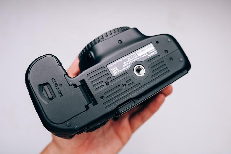
The Canon AE-1, introduced in 1976, is a legendary 35mm film SLR camera celebrated for its durability, intuitive design, and advanced features. It combines manual control with automatic modes, making it accessible to both professionals and hobbyists. The camera features a manual film transport system, shutter speeds from 2 seconds to 1/1000th of a second, and an aperture priority mode. Its error-proof operation and reliability have made it a favorite among photographers. The AE-1’s design and functionality continue to inspire enthusiasts, ensuring its place in photography history.

1.2 Importance of the Manual for Users

The Canon AE-1 manual is essential for understanding the camera’s operation, features, and maintenance. It provides detailed instructions for using automatic and manual modes, troubleshooting common issues, and maintaining the camera’s longevity. Whether you’re a novice or an experienced photographer, the manual serves as a comprehensive guide to unlocking the AE-1’s full potential. It ensures optimal performance, helps resolve technical problems, and offers tips for preserving the camera’s condition, making it an indispensable resource for all users.

Features of the Canon AE-1

The Canon AE-1, introduced in 1976, is a 35mm SLR featuring a built-in TTL metering system, three operational modes, and compatibility with FD-mount lenses, ensuring reliability and versatility.

2.1 Key Components and Controls

  • The Canon AE-1 features a 35mm film format with an FD lens mount, ensuring compatibility with a wide range of lenses.
  • The camera includes a built-in TTL (Through-The-Lens) metering system for accurate exposure control.
  • Key controls include the aperture ring, shutter speed dial, and ASA dial for film sensitivity settings.
  • The film advance lever and battery compartment are conveniently located for easy access.
  • The viewfinder provides clear visibility with a microprism spot for precise focusing.
  • Three operational modes—Programmed AE, Shutter-Speed Priority, and Manual Override—are accessible via intuitive controls.

2.2 Advanced Functionalities

The Canon AE-1 offers advanced functionalities that enhance photography experiences. It features three exposure modes: Programmed AE for automatic settings, Shutter-Speed Priority for manual control over shutter speed, and Manual Override for precise adjustments. The camera also includes a built-in flash system with E-TTL II compatibility for accurate flash exposure. Additionally, the AE-1 supports motor drive attachments for faster film advancement and continuous shooting. Its compatibility with a wide range of FD-series lenses ensures versatility for various photographic needs, making it a powerful tool for both amateurs and professionals.

Operational Modes of the Canon AE-1

The Canon AE-1 operates in three modes: Programmed AE, Shutter-Speed Priority, and Manual Override, offering flexibility for automatic and manual control over exposures. This versatility caters to diverse shooting needs and skill levels, ensuring precision and creativity in photography.

3.1 Programmed AE Mode

In Programmed AE Mode, the Canon AE-1 automatically sets both aperture and shutter speed for optimal exposure, making it ideal for beginners and professionals alike. This mode ensures balanced settings across various lighting conditions, allowing users to focus solely on composition and subject matter. It’s a convenient and time-saving feature that leverages the camera’s advanced automation to deliver consistent results, while still offering the flexibility to override settings when desired. This mode is particularly useful for capturing sharp, well-exposed images in dynamic environments.

3.2 Shutter-Speed Priority AE Mode

In Shutter-Speed Priority AE Mode, users can manually set the shutter speed, while the camera automatically adjusts the aperture for optimal exposure. This mode is ideal for controlling motion effects, such as freezing fast-moving subjects or creating artistic blur. With shutter speeds ranging from 2 seconds to 1/1000th of a second, photographers can achieve precise control over motion and light. The AE-1’s automation ensures balanced exposure, making it versatile for various lighting conditions while maintaining creative control over timing and effects. This mode is particularly useful for action photography and artistic expression.

3.3 Manual Override Mode

The Manual Override Mode allows photographers to bypass automatic settings, offering full control over both shutter speed and aperture. This mode is ideal for experienced users who prefer precise adjustments to achieve specific creative effects. By disabling the camera’s automation, users can manually set exposures, enabling greater artistic control and customization. The AE-1’s manual mode is particularly useful in challenging lighting conditions or when a specific aesthetic is desired, making it a powerful tool for advanced photographers seeking ultimate creative freedom and technical precision.

Troubleshooting Common Issues

Identify and resolve common problems like shutter malfunctions or exposure errors. Clean the camera’s components and ensure proper battery installation for optimal performance.

4.1 Resolving Shutter and Exposure Problems

Shutter issues may arise from dirt or worn parts. Clean the shutter blades gently with a soft brush. For exposure problems, check the light meter’s accuracy and ensure correct ISO settings. If issues persist, consult a professional technician. Regular maintenance can prevent these common problems, ensuring your Canon AE-1 operates smoothly and delivers precise exposures.

4.2 Addressing Battery and Power Issues

The Canon AE-1 uses a 6V silver-oxide battery (eveready 544 or equivalent). If the camera doesn’t power on, ensure the battery is installed correctly and the compartment latch is secure. Use a small screwdriver to push in the latch if necessary. Clean the battery contacts with a soft cloth to maintain good connectivity. If issues persist, check for corrosion or replace the battery. For persistent power problems, consult a professional technician to diagnose and repair any internal electrical faults;

Maintenance and Care Tips

Regularly clean the lens and viewfinder with a soft cloth. Store the camera in a dry, cool place to prevent damage. Avoid exposing it to extreme temperatures or moisture to ensure optimal performance and longevity.

5.1 Cleaning and Storage Guidelines

Use a soft, dry cloth to clean the lens and viewfinder. Avoid harsh chemicals or abrasive materials that may damage surfaces. Store the camera in a cool, dry place away from direct sunlight. Use a protective case to prevent scratches and dust accumulation. Ensure the camera is turned off and film is removed before storage. Regular cleaning prevents dust buildup, ensuring optimal performance. For long-term storage, consider using silica gel packets to maintain dry conditions. Always handle the camera with care to extend its lifespan and maintain functionality.

5.2 Preventing Damage and Extending Lifespan

Avoid exposing the camera to extreme temperatures or mechanical stress. Use silica gel packets to maintain dry storage conditions. Handle the camera gently to prevent scratches or dents. Always use the lens cap when not shooting to protect the lens from dust and damage. Regularly inspect and clean battery terminals to prevent corrosion. For complex repairs, consult a professional to avoid further damage. Proper care ensures the Canon AE-1 remains functional and reliable for years to come.

Resources and Support

Access official Canon AE-1 manuals and guides on www.canon.com/icpd. Visit authorized service centers like Manhattan Service Center or Atlanta Office for expert assistance and repairs.

6.1 Accessing Official Canon Manuals and Guides

Official Canon AE-1 manuals and guides are available on the Canon website at www.canon.com/icpd. Users can download PDF versions of instruction manuals, pocket guides, and troubleshooting resources. Additional materials, such as service manuals and user-contributed content, can be found on third-party sites like www.baytan.org and www.butkus.us. These resources provide detailed information on camera operations, maintenance, and repair, ensuring comprehensive support for AE-1 users worldwide.

6.2 Finding Service Centers and Expert Assistance

Canon AE-1 users can locate authorized service centers through Canon’s official website or regional offices like the Manhattan Service Center in New York. Additional assistance is available at centers such as the Atlanta Office in Georgia. Expert help is also accessible through Canon’s customer support channels. For specialized repairs, users may contact trusted third-party repair services or photography communities. These resources ensure professional maintenance and repair for the AE-1, preserving its functionality and longevity.

The Canon AE-1 remains a reliable, user-friendly camera with advanced features. Proper care and maintenance ensure its longevity, making it a timeless choice for photographers.

7.1 Summary of Key Points

The Canon AE-1 is a legendary camera offering ease of use and advanced functionalities. Its manual provides detailed guidance for optimal performance, ensuring photographers master its capabilities. Key features include multiple shooting modes and durable construction. Regular maintenance and proper care extend its lifespan. Whether for beginners or professionals, the AE-1 remains a versatile tool, combining simplicity with sophistication. By following the manual’s instructions, users can unlock its full potential and capture high-quality images effortlessly.

7.2 Final Tips for Maximizing Camera Potential

To fully utilize the Canon AE-1, regularly clean the lens and viewfinder for optimal clarity. Experiment with different shooting modes to understand their effects. Store the camera in a cool, dry place to prevent damage. Familiarize yourself with the manual for troubleshooting and advanced techniques. Always check battery levels before use and consider using original Canon accessories for compatibility. By following these tips, you can enhance your photography experience and ensure the AE-1 performs at its best for years to come.

Bycassandre

dmc zs100 manual

The Panasonic Lumix DMC-ZS100 is a high-performance compact camera featuring a 1-inch 20.1MP sensor, 10x optical zoom, and 4K capabilities, ideal for enthusiasts and travelers. Its manual is essential for mastering both basic and advanced functions, ensuring users unlock its full potential.

1.1 Overview of the Camera

The Panasonic Lumix DMC-ZS100 is a compact, high-performance camera featuring a 20.1MP 1-inch MOS sensor, 10x optical zoom, and 4K video/photo capabilities. Designed for versatility, it balances portability with advanced imaging technology, making it ideal for travel and everyday photography. The camera’s intuitive design and robust feature set cater to both enthusiasts and casual shooters, supported by a comprehensive manual.

1.2 Importance of the Manual

The manual is crucial for unlocking the Panasonic Lumix DMC-ZS100’s full potential, providing detailed instructions for both basic and advanced features. It guides users through camera settings, shooting modes, and troubleshooting, ensuring optimal performance. Whether for beginners or enthusiasts, the manual serves as an essential resource for mastering the camera’s capabilities and enhancing photography experiences.

Key Features of the Panasonic Lumix DMC-ZS100

The Panasonic Lumix DMC-ZS100 features a 20.1MP 1-inch MOS sensor, LEICA DC VARIO-ELMARIT 10x optical zoom, and 4K video/photo capabilities, offering exceptional image quality and versatility;

2.1 20.1-Megapixel 1-Inch MOS Sensor

The Panasonic Lumix DMC-ZS100 features a 20.1-megapixel 1-inch MOS sensor, significantly larger than sensors in most compact cameras, delivering excellent low-light performance, high sensitivity, and detailed images. Paired with the Venus Engine, it ensures natural colors, reduced noise, and crisp clarity, making it ideal for capturing high-quality photos in various lighting conditions.

2.2 LEICA DC VARIO-ELMARIT 10x Optical Zoom Lens

The LEICA DC VARIO-ELMARIT lens offers a 10x optical zoom (25-250mm equivalent), providing versatility for wide-angle to telephoto photography. Its high-quality design ensures sharp images with minimal distortion, while the large aperture enables better low-light performance. This lens is ideal for capturing detailed landscapes, portraits, and distant subjects with precision and clarity, making it a standout feature of the DMC-ZS100.

2.3 4K Video and Photo Capabilities

The DMC-ZS100 excels with 4K video recording at 30fps, delivering high-resolution footage. Its 4K Photo mode captures 8MP images from video, perfect for action shots. Additionally, the Post Focus feature allows adjusting focus after shooting, enhancing creative control. These capabilities make it ideal for capturing detailed videos and stills with precision and versatility, catering to both enthusiasts and professionals alike.

Downloading the DMC-ZS100 Manual

The Panasonic Lumix DMC-ZS100 manual is available for download on Panasonic’s official website; It includes basic and advanced guides, ensuring comprehensive understanding of the camera’s features.

3.1 Sources for the Manual

The Panasonic Lumix DMC-ZS100 manual can be sourced from the official Panasonic website, offering both basic and advanced guides. Authorized retailers and third-party sites like ManualsLib also provide access. Additionally, reaching out to Panasonic’s customer support or checking forums and associated apps may offer alternative sources for the manual, ensuring a comprehensive understanding of the camera’s features and operation.

3.2 How to Access the PDF Version

To access the PDF version of the Panasonic Lumix DMC-ZS100 manual, visit the official Panasonic website. Navigate to the support section, select your camera model, and download the manual directly. It is also available on trusted third-party sites like ManualsLib. The PDF format ensures easy reading and printing, providing comprehensive guidance for both basic and advanced camera operations.

Understanding the Manual Structure

The Panasonic Lumix DMC-ZS100 manual is a comprehensive guide covering 406 pages, applicable to both DMC-ZS100 and DMC-ZS60 models. It is organized into sections for basic and advanced features, with the advanced manual available in PDF format for more detailed instructions.

4.1 Table of Contents

The manual begins with an introduction, followed by key features and shooting modes. It details image quality settings, connectivity options, maintenance tips, and troubleshooting. Advanced features like RAW capture and focus stacking are also covered. The table of contents is logically organized, ensuring easy navigation for users to find specific sections quickly and efficiently.

4.2 Basic vs. Advanced Features

The manual divides the camera’s functionality into basic and advanced features. Basic features cover essential operations like automatic mode, image settings, and connectivity, while advanced features delve into manual controls, RAW capture, and specialized shooting modes. This structure allows users to gradually explore complex functions, making the manual accessible to both beginners and experienced photographers alike.

Camera Controls and Layout

The DMC-ZS100 features an intuitive design with external controls, including zoom, video recording, and navigation buttons, allowing easy access to settings and modes for seamless operation.

5.1 External Controls and Buttons

The Panasonic Lumix DMC-ZS100 features a range of external controls designed for intuitive operation. Key buttons include the shutter release, zoom lever, video recording button, and navigation controls. The mode dial allows quick access to shooting modes, while function buttons enable customization. Ergonomic design ensures easy handling, with controls positioned for quick access to settings and features, enhancing the shooting experience.

5.2 Customization Options

The Panasonic Lumix DMC-ZS100 offers extensive customization options, allowing users to tailor the camera to their preferences. The function buttons can be assigned to frequently used settings, and the Quick Menu provides rapid access to key features. Additionally, custom shooting modes enable users to save preferred settings for quick recall, enhancing flexibility and efficiency during photography sessions.

Shooting Modes

The Panasonic Lumix DMC-ZS100 offers a variety of shooting modes, including Automatic, Manual, and 4K Photo, providing flexibility for different situations and user preferences, ensuring optimal results.

6.1 Automatic Mode

The Automatic Mode on the Panasonic Lumix DMC-ZS100 simplifies photography for beginners, automatically adjusting settings like exposure, ISO, and focus. It leverages advanced features like Intelligent Auto (iA) and Mega O.I.S. for stabilization, ensuring sharp, well-balanced images in various lighting conditions. This mode is ideal for quick, hassle-free shooting, allowing users to capture moments without manual adjustments.

6.2 Manual Mode

Manual Mode on the Panasonic Lumix DMC-ZS100 offers extensive control over settings like aperture, shutter speed, and ISO, enabling precise adjustments for creative photography. It allows users to fine-tune exposure compensation and focus, providing flexibility for capturing unique lighting and depth-of-field effects. This mode is ideal for enthusiasts seeking advanced control to enhance their artistic vision and technical precision in various shooting scenarios.

6.3 Specialized Modes (e.g., 4K Photo)

The Panasonic Lumix DMC-ZS100 features specialized modes like 4K Photo, allowing users to extract 8MP images from 4K video. Focus Stacking enables combining multiple images for extended depth of field. These modes enhance creativity, making them ideal for capturing fleeting moments or achieving precise focus in macro photography, while ensuring high-quality results tailored to specific shooting scenarios and artistic visions.

Image and Video Quality Settings

The DMC-ZS100 allows adjusting image quality settings, such as resolution and compression, while video recording options include 4K resolution and frame rate adjustments for optimal results.

7.1 Adjusting Image Quality

The Panasonic Lumix DMC-ZS100 allows users to adjust image quality settings, including resolution, compression, and aspect ratio. The camera supports various JPEG settings and RAW image capture for advanced editing. Users can fine-tune settings like noise reduction and sharpening to optimize image output. These adjustments ensure high-quality photos, even in challenging lighting conditions, making it ideal for enthusiasts seeking precise control over their imagery.

7.2 Video Recording Options

The Panasonic Lumix DMC-ZS100 offers versatile video recording options, including 4K resolution at 30fps and 1080p at 60fps. Users can also utilize the 4K Photo mode to extract high-quality still images from video footage. The camera supports various frame rates and resolution settings, allowing for customization to suit different creative needs.

The manual provides detailed instructions on adjusting video settings, such as stabilization and audio levels, to enhance recording quality and ensure optimal results in different scenarios.

Connectivity and Sharing

The Panasonic Lumix DMC-ZS100 features Wi-Fi and Bluetooth connectivity, enabling seamless file transfers to smartphones and tablets via the Panasonic Image App for quick sharing and backup.

8.1 Wi-Fi and Bluetooth Integration

The Panasonic Lumix DMC-ZS100 integrates Wi-Fi and Bluetooth for seamless connectivity. Users can transfer images and videos to smartphones or tablets using the Panasonic Image App, enabling quick sharing on social media. Bluetooth Low Energy ensures stable connections and allows for remote camera control, enhancing convenience for enthusiasts and professionals alike.

8.2 Transferring Files to Smartphones

The Panasonic Lumix DMC-ZS100 allows quick and easy file transfers to smartphones via Wi-Fi. Using the Panasonic Image App, users can wirelessly send photos and videos to their devices for instant sharing on social media. This feature enhances workflow efficiency and ensures memories are easily accessible and shareable, compatible with both iOS and Android devices for universal convenience.

Maintenance and Care

Regularly clean the lens and camera body with a soft cloth to prevent scratches. Store in a dry, cool place to avoid moisture damage and ensure longevity.

9.1 Cleaning the Camera

Use a soft, dry cloth to gently wipe the camera body and lens to remove fingerprints and smudges. For stubborn marks, dampen the cloth slightly with water, but avoid harsh chemicals. Clean the LCD screen with a microfiber cloth, ensuring no moisture seeps into the camera. Regular cleaning prevents damage and maintains image quality. Store the camera in a protective case when not in use to prevent scratches and dust accumulation.

9.2 Avoiding Damage

Avoid exposing the camera to extreme temperatures, moisture, or physical stress. Use the flash only in dry conditions, and stop immediately if it sparks. Store the camera in a protective case, away from direct sunlight and humidity. Avoid touching the lens or sensor to prevent scratches or smudges, and use a high-quality memory card to ensure reliable performance and prevent data loss.

Troubleshooting Common Issues

Address error messages by checking connections or resetting the camera. Flash malfunctions may require cleaning or professional servicing. Refer to the manual for detailed solutions.

10.1 Resolving Error Messages

Resolve error messages by checking connections, resetting the camera, or cleaning components. Refer to the manual for specific solutions. For example, “E0001” indicates a lens issue, while “E0002” points to card errors. Restarting the camera often fixes temporary glitches. If problems persist, consult the troubleshooting section or contact support for assistance. Always ensure the camera is updated to the latest firmware version.

10.2 Addressing Flash Malfunctions

If the flash malfunctions, stop using it immediately to avoid damage. Clean the flash area gently with a soft cloth and ensure proper battery connections. Update the camera firmware to resolve software-related issues. If problems persist, refer to the troubleshooting guide or contact Panasonic support for professional assistance. Always follow safety guidelines to prevent further damage or electrical hazards.

Advanced Features for Enthusiasts

The DMC-ZS100 offers advanced features like RAW image capture, enabling detailed post-processing, and focus stacking for precise depth control, catering to enthusiasts seeking professional-grade functionality in a compact design.

11.1 RAW Image Capture

The Panasonic Lumix DMC-ZS100 supports RAW image capture, allowing photographers to save uncompressed files for greater flexibility in post-processing. This feature is particularly beneficial for enthusiasts, as it retains maximum image detail and enables precise control over editing parameters like white balance and noise reduction. RAW files can be processed using specialized software, ensuring optimal image quality and creative control. This advanced capability enhances the camera’s appeal for professional-grade photography.

11.2 Focus Stacking

Focus Stacking on the Panasonic Lumix DMC-ZS100 allows users to combine multiple images with varying focus points, creating a single image with extended depth of field. This feature is particularly useful for macro photography, where achieving sharp focus across a scene is challenging. By capturing several shots at different focus positions, enthusiasts can merge them later using post-processing software, resulting in professional-grade images with precise control over depth and clarity.

User Reviews and Feedback

Users praise the Panasonic Lumix DMC-ZS100 for its exceptional image quality, portability, and 4K capabilities. The manual is lauded for its clarity, though some wish for more detailed advanced mode explanations.

12.1 Strengths of the DMC-ZS100

The Panasonic Lumix DMC-ZS100 excels with its 1-inch 20.1MP sensor, delivering crisp images in low light. Its LEICA lens and 10x zoom offer versatility, while 4K capabilities enhance video and photo capture. Portability and intuitive controls make it ideal for travel, and the manual provides clear guidance for both novice and advanced users, ensuring optimal performance across various modes.

12.2 Areas for Improvement

While the DMC-ZS100 excels in many areas, some users note room for enhancement. Autofocus speed in low-light conditions could be improved, and manual focus during 4K video would add versatility. The lack of weather sealing and a headphone jack limits its appeal for professionals. Additionally, battery life could be extended to support full-day shooting sessions without recharging.

The Panasonic Lumix DMC-ZS100 is a versatile and powerful camera, offering excellent image quality and 4K capabilities in a compact design. Its comprehensive manual ensures users maximize its potential, making it a standout choice for both casual and advanced photographers.

13.1 Final Thoughts on the DMC-ZS100

The Panasonic Lumix DMC-ZS100 is a remarkable camera, blending portability with advanced features like a 1-inch sensor and 4K capabilities. Its intuitive design and comprehensive manual make it accessible to all users. Whether for casual snapshots or professional-grade photography, the DMC-ZS100 delivers exceptional results, proving to be a versatile tool for capturing life’s moments with precision and creativity.

13.2 Encouragement to Explore Further

With the DMC-ZS100, the possibilities for creative photography and videography are vast. Encourage yourself to delve deeper into its features, such as RAW capture and 4K Photo mode, to elevate your imaging skills. Experiment with manual controls, explore advanced settings, and stay updated with firmware updates to maximize its potential and continue capturing stunning moments with ease and precision;

Bycassandre

gm9s80 installation manual

This manual provides detailed instructions for installing the GM9S80 furnace‚ ensuring compliance with safety standards and optimal performance․ It covers essential steps‚ from pre-installation checks to final testing‚ and includes troubleshooting tips for a smooth setup․ Proper installation is crucial for efficiency and safety․

Welcome to the GM9S80 Installation Manual․ This guide is designed to assist qualified personnel in the safe and proper installation‚ maintenance‚ and operation of the GM9S80 gas furnace․ The manual provides detailed instructions and essential information to ensure compliance with safety standards and manufacturer recommendations․ Proper installation is critical to achieve optimal performance‚ efficiency‚ and reliability of the unit․

Before proceeding‚ it is imperative to read this manual thoroughly and understand all safety precautions‚ installation requirements‚ and operational guidelines․ The GM9S80 is a high-efficiency gas furnace designed for residential use‚ and its installation must comply with local‚ state‚ and national codes and regulations․ Failure to follow the instructions in this manual may result in unsafe conditions‚ reduced system performance‚ or void the warranty․

This manual is intended for licensed professionals‚ including HVAC technicians and installers‚ who have the necessary expertise to handle gas furnace installations․ Always follow safety precautions‚ such as turning off power and gas supplies before starting work․ Proper installation and maintenance are key to preventing potential hazards and ensuring the furnace operates efficiently for years to come․ Refer to the specific sections of this manual for detailed procedures and guidelines․

Safety Precautions

Safety is paramount when installing and maintaining the GM9S80 gas furnace․ This section outlines essential precautions to ensure a safe working environment and prevent potential hazards․ Always follow local‚ state‚ and national safety codes‚ as well as manufacturer guidelines․

  • Ensure the furnace is installed by a licensed professional․ Improper installation can lead to safety risks‚ reduced efficiency‚ or equipment damage․
  • Turn off the main power and gas supply before starting any installation or maintenance work․ Verify the power is off using a voltage tester․
  • Use proper personal protective equipment (PPE)‚ such as safety glasses and gloves‚ when handling electrical or gas components․
  • Never tap or force the pressure switch to close‚ as this can cause system damage or create unsafe operating conditions․
  • Ensure proper ventilation and combustion air supply to avoid carbon monoxide buildup or incomplete combustion․
  • Keep the installation area clean and free from flammable materials to minimize fire risks․
  • Follow all electrical connection guidelines to prevent shock or arcing․ Check for tightness and inspect wires for damage before energizing the system․

Failure to adhere to these precautions may result in injury‚ property damage‚ or void the product warranty․ Always refer to local regulations and the manufacturer’s instructions for specific requirements․ Safety is everyone’s responsibility‚ and proper installation practices are critical to ensuring long-term reliability and performance of the GM9S80 furnace․

Pre-Installation Checks

Before proceeding with the installation of the GM9S80 gas furnace‚ perform the following pre-installation checks to ensure a smooth and successful setup․ These steps are critical to verify compatibility‚ safety‚ and proper system operation․

  • Site Preparation: Confirm the installation location is clear of obstructions and meets the spatial requirements outlined in the manual․ Ensure the area is clean‚ dry‚ and free from flammable materials․
  • Equipment Compatibility: Verify that the furnace model is suitable for the building’s specifications‚ including heating load requirements and ventilation capabilities․
  • Local Regulations: Check local building codes‚ gas and electrical regulations‚ and environmental standards to ensure compliance․
  • Electrical and Gas Supply: Confirm the availability of a properly sized electrical circuit and a gas supply line that meets the furnace’s specifications․ Inspect wires for damage and ensure connections are secure․
  • Ductwork and Ventilation: Inspect the duct system for leaks‚ damage‚ or obstructions․ Ensure proper venting and combustion air intake are feasible based on the furnace’s requirements․
  • Filters and Accessories: Check if the correct filters and accessories are available and compatible with the GM9S80 model․
  • Manuals and Documentation: Ensure all necessary manuals‚ instructions‚ and warranty information are on hand for reference during installation․

Addressing these pre-installation checks ensures the furnace is installed correctly‚ operates efficiently‚ and meets safety standards․ Any issues identified during this phase should be resolved before proceeding with the installation process․

Installation Location and Preparation

Choosing the correct location and properly preparing the site are essential for the safe and efficient operation of the GM9S80 gas furnace․ Ensure the installation location meets the following criteria:

  • Location Requirements: Install the furnace in a well-ventilated area‚ away from flammable materials and sensitive equipment․ The location must comply with local building codes and safety regulations․
  • Drainage and Water Protection: Ensure the area is protected from water damage or flooding․ The furnace should not be installed in areas prone to moisture accumulation․
  • Accessibility: The furnace should be installed in an accessible location to facilitate maintenance‚ repairs‚ and inspections․ Ensure there is adequate space around the unit for proper airflow and servicing․
  • Orientation: The GM9S80 can be installed in either a horizontal or vertical configuration‚ depending on the application․ Ensure the unit is level and securely anchored to prevent vibration or movement․
  • Clearance Requirements: Maintain the minimum clearance specified in the manual from combustible materials and obstructions․ Proper clearance ensures safe operation and prevents overheating․
  • Preparation Steps: Clean the installation area thoroughly and ensure the surface is level․ If installing horizontally‚ ensure the burner doors are oriented correctly to fire into the heat exchanger․ For vertical installations‚ verify the venting and combustion air systems are properly configured․

Proper site preparation and location selection are critical to ensure the furnace operates safely and efficiently․ Always follow the manufacturer’s guidelines and local regulations when preparing the installation site․

Electrical Connections

Proper electrical connections are critical for the safe and efficient operation of the GM9S80 gas furnace․ Follow these steps to ensure correct wiring:

  • Power Supply: Verify that the electrical supply matches the furnace’s voltage and amperage requirements‚ as specified in the manual․ Ensure the circuit breaker or fuse box is appropriately rated․
  • Wiring Inspection: Check all wires for signs of damage‚ fraying‚ or corrosion․ Replace any damaged wiring to prevent electrical hazards․
  • Connections: Ensure all electrical connections are tight and secure․ Loose connections can lead to malfunction or safety risks․
  • Grounding: Confirm that the furnace is properly grounded to prevent electrical shock and ensure safe operation․
  • Control Circuit: Verify the low-voltage control circuit is correctly connected‚ as it controls the furnace’s ignition‚ safety devices‚ and operation․
  • Testing: After completing the connections‚ test the system to ensure proper function․ Use a multimeter to check for continuity and voltage as needed․

Always refer to the GM9S80 installation manual for specific wiring diagrams and detailed instructions․ Adhere to local electrical codes and safety standards to ensure a safe and reliable installation․

Gas Connections

Proper gas connections are essential for the safe and efficient operation of the GM9S80 gas furnace․ Follow these steps to ensure accurate installation:

  1. Gas Supply Line: Verify that the gas supply line is appropriately sized and compatible with the furnace’s requirements․ Ensure it is free from damage or leaks․
  2. Shut-Off Valve: Install a gas shut-off valve near the furnace for easy access in case of emergencies․ Ensure it is turned off during installation․
  3. Connection Points: Use approved gas-rated fittings and pipe sealants to secure connections․ Avoid using Teflon tape‚ as it can contaminate the system․
  4. Leak Testing: After connecting the gas line‚ perform a leak test using soapy water or an approved leak-detection solution․ Bubbles indicate a leak‚ which must be repaired immediately․
  5. Gas Type: Confirm that the furnace is configured for the correct gas type (natural or propane)․ Refer to the manual for specific settings or adjustments․
  6. Pressure Check: Ensure the gas pressure matches the furnace’s specifications․ Use a manometer to verify pressure levels․
  7. Compliance: Ensure all connections comply with local gas codes and safety standards․ Consult a licensed professional if unsure․

Never skip any steps‚ as improper gas connections can lead to safety hazards or system malfunction․ Always refer to the GM9S80 installation manual for specific instructions and diagrams․

Venting and Combustion Air

Proper venting and combustion air setup are critical for the safe and efficient operation of the GM9S80 gas furnace․ Follow these guidelines to ensure correct installation:

Venting System: The venting system must be designed to handle combustion byproducts like carbon monoxide safely․ Use approved venting materials‚ such as stainless steel or PVC‚ depending on the furnace’s requirements․ Ensure all vent pipes are properly sealed and sloped to prevent gas leaks or condensation buildup․

Vent Termination: The vent termination must be installed at least 12 inches above the roof or 3 feet away from any adjacent windows or doors to prevent recirculation of exhaust gases․ Use a vent cap to protect against weather and debris․

Combustion Air: Ensure adequate combustion air is available for proper burner operation․ If the furnace is installed in a confined space‚ provide a dedicated combustion air intake or ensure the room meets minimum airflow requirements․ Direct venting systems are recommended for tight spaces․

Combustion Air Opening: If a combustion air opening is required‚ size it according to local building codes and the furnace’s specifications․ Ensure it is not obstructed and provides clear airflow from outside the building․

Testing: After installation‚ test the venting system for leaks and ensure proper draft․ Use a manometer to verify vent pressure and airflow rates․

Always adhere to local building codes and the GM9S80 installation manual for specific venting and combustion air requirements․ Improper setup can lead to safety hazards or reduced furnace performance․

Post-Installation Testing

After completing the installation of the GM9S80 gas furnace‚ perform thorough post-installation testing to ensure proper operation and safety․ This step is crucial for identifying any issues before the system is put into regular use․

Power and Ignition Test: Verify that the furnace powers on and ignites correctly․ Check the igniter and flame sensor for proper function․ Ensure the burner lights and maintains a steady flame․ If the flame appears unstable or the igniter fails‚ inspect the wiring and gas connections․

Temperature Rise Test: Measure the temperature rise across the heat exchanger using a thermocouple or digital thermometer․ Compare the readings to the manufacturer’s specifications to ensure the furnace is operating within safe and efficient parameters․

Gas Leak Test: Conduct a gas leak test on all connections using a soap solution or electronic gas detector․ Bubbles or alarms indicate potential leaks that need immediate attention․

Venting and Draft Test: Use a manometer to measure vent pressure and ensure proper draft․ Check for any blockages or restrictions in the venting system that could impede airflow․

Control and Safety Test: Test all safety controls‚ including the pressure switch‚ high-limit switch‚ and roll-out switches․ Simulate fault conditions to ensure the system shuts down properly when safety limits are exceeded․

Final Inspection: Inspect all components‚ including filters‚ drains‚ and electrical connections‚ to ensure they are secure and functioning as intended; Document the test results and address any anomalies before finalizing the installation․

Post-installation testing ensures the GM9S80 operates safely and efficiently‚ meeting both manufacturer specifications and industry standards․ Any issues identified during this phase should be corrected promptly to prevent future malfunctions or safety hazards․

Maintenance and Troubleshooting

Regular maintenance is essential to ensure the GM9S80 operates efficiently and safely․ Perform routine checks to identify and address potential issues before they escalate․ Always refer to the manufacturer’s guidelines for specific maintenance procedures․

  • Filter Cleaning/Replacement: Inspect and clean or replace the air filters monthly․ Dirty filters reduce airflow‚ decreasing efficiency and potentially causing system malfunctions․
  • Heat Exchanger Inspection: Annually inspect the heat exchanger for cracks or corrosion․ Damage to this component can lead to dangerous carbon monoxide leaks and requires immediate repair․
  • Venting System Check: Ensure the venting system is free from blockages‚ such as nests or debris․ Proper venting is critical for safe operation and combustion air supply․
  • Electrical Connections: Verify that all electrical connections are secure and free from corrosion․ Loose connections can cause intermittent operation or complete system failure․

Troubleshooting Tips:

  • If the inducer motor runs but the pressure switch does not close‚ check for blockages in the venting system or ensure the draft is within specifications․ Lightly tapping the pressure switch may temporarily resolve the issue but requires professional attention․
  • If the furnace fails to ignite‚ inspect the igniter and flame sensor for cleanliness and proper alignment․ Ensure the gas valve is fully open and there are no gas supply issues․
  • For recurring issues‚ consult the troubleshooting chart in the manual or contact a qualified technician․ Never attempt repairs beyond your expertise‚ as this could void the warranty or compromise safety․

By following a consistent maintenance schedule and addressing issues promptly‚ you can extend the lifespan of the GM9S80 and ensure reliable performance․ Always prioritize safety and refer to the manual for detailed instructions․

Final Checks and Customer Instructions

After completing the installation‚ perform a thorough system test to ensure all components function correctly․ Verify proper gas flow‚ ignition‚ and heating operation․ Check for any gas leaks using a soap solution or electronic detector‚ and ensure all electrical connections are secure․

  • System Operation Test: Run the furnace through multiple cycles to confirm consistent performance․ Monitor for unusual noises‚ vibrations‚ or odors‚ which could indicate installation issues․
  • Customer Instructions: Provide the homeowner with a comprehensive overview of the system‚ including operating instructions‚ maintenance requirements‚ and safety features․
  • Safety Precautions: Emphasize the importance of keeping the furnace area clear of flammable materials and ensuring proper ventilation․ Advise the customer to install carbon monoxide detectors for added safety․
  • Manual Handover: Leave a copy of the GM9S80 installation manual with the customer for future reference․ Highlight key sections‚ such as troubleshooting and maintenance schedules․

Ensure the customer understands how to operate the thermostat and recognize normal system behavior․ Address any concerns or questions they may have to ensure they feel confident using their new furnace․ A well-informed customer is better equipped to maintain the system and address minor issues promptly․

Finally‚ confirm that all installation documentation‚ including warranties and service contacts‚ is provided to the customer․ This ensures they have all necessary resources for future service needs․

Bycassandre

ems foot massager manual pdf

Welcome to the comprehensive guide for your EMS Foot Massager. This manual provides essential information for safe and effective use, ensuring optimal benefits and prolonged device lifespan.

Overview of the EMS Foot Massager

The EMS Foot Massager is a portable, innovative device designed to provide relaxing and therapeutic massages for your feet and calves. It utilizes Electrical Muscle Stimulation (EMS) technology to improve blood circulation, relieve muscle tension, and enhance overall foot health. With multiple massage modes, such as kneading, scraping, and acupuncture, this device offers customizable experiences tailored to your needs. Featuring adjustable intensity levels, it caters to both gentle and intense massage preferences. Compact and user-friendly, the EMS Foot Massager is an ideal solution for home or office use, promoting relaxation and well-being with minimal effort.

Importance of Reading the Manual

Reading the EMS Foot Massager manual is essential for safe and effective use. It provides detailed instructions on operating the device, understanding its features, and troubleshooting common issues. The manual also outlines safety precautions, such as contraindications for use and recommended session durations, to ensure your well-being. By following the guidelines, you can maximize the benefits of the massager while minimizing potential risks. Proper usage ensures optimal performance and longevity of the device. Always consult the manual before first use to familiarize yourself with its functions and maintenance requirements.

Key Features of the EMS Foot Massager

The EMS Foot Massager offers multiple massage modes, adjustable intensity levels, and advanced stimulation technology to enhance comfort and improve blood circulation effectively.

Massage Modes and Intensity Levels

The EMS Foot Massager features multiple massage modes, including Massage, Knead, Scrape, Elbow Pressing, Acupuncture, and Cupping Jar. Each mode provides a unique stimulation experience. The device also offers 9 adjustable intensity levels, ranging from gentle to intense, allowing users to customize their experience based on comfort and preference. To adjust intensity, press the designated button to increase or decrease the level. The massager operates at a frequency of 1-100Hz, ensuring effective muscle stimulation and improved blood circulation. Always start with a lower intensity and gradually increase as needed for optimal comfort and results.

Technical Specifications

  • Voltage: Operates at DC 5V for safe and efficient performance.
  • Input Power: Consumes 2.5W, ensuring low energy usage.
  • Working Temperature: Ideal operation between 15°C and 35°C.
  • Auto Shut-off: Device turns off automatically after 20 minutes of use.
  • Frequency: Adjusts between 1-100Hz for customizable stimulation.
  • Weight: Lightweight design at 3.5 lbs for easy portability.

These specifications ensure reliable performance and user safety while providing an effective massage experience.

How to Use the EMS Foot Massager

Place your feet on the mat, press the power button, and select your preferred mode and intensity. Start with low settings and adjust as needed for comfort.

Step-by-Step Setup and Operation

Unbox and assemble the device if required. Ensure all components are intact. 2. Place the foot mat on a flat surface and position the main unit securely. 3. Turn on the device using the power button. 4. Select your preferred massage mode using the mode button (e.g., massage, knead, scrape). 5. Adjust the intensity level using the designated buttons, starting low and increasing as needed. 6. Place your bare feet on the mat, ensuring good contact with the electrodes. 7. Relax and let the device work. The session will auto-shutoff after 20 minutes. Adjust settings mid-session if desired for comfort.

Adjusting Intensity and Mode Settings

To personalize your experience, start by selecting one of the 6 massage modes (e.g., Massage, Knead, Scrape) using the mode button. Once a mode is chosen, use the intensity buttons to adjust the strength of the stimulation. Begin at a low intensity and gradually increase to your comfort level. The device offers 9 intensity levels, ensuring a customizable experience. If you switch modes, the intensity will reset to level 0 for safety. Experiment with different combinations to find your preferred setting, enhancing relaxation and muscle relief. Adjustments can be made during the session for optimal comfort.

Safety Precautions and Guidelines

Avoid using the EMS Foot Massager for more than 20 minutes per session. Stop immediately if discomfort or unusual sensations occur and consult a healthcare professional.

Contraindications for Use

The EMS Foot Massager is not recommended for individuals with certain medical conditions. Those with pacemakers, pregnant women, or people with metal implants should avoid using the device. Additionally, individuals with open wounds, cancer, or sensitive areas should not use it. The massager should not be applied to inflamed tissues or areas with poor circulation. Always consult a healthcare professional before use if you have any underlying medical conditions or concerns. Adhering to these guidelines ensures safe and effective use of the EMS Foot Massager.

Recommended Usage Duration

For optimal results and safety, use the EMS Foot Massager for a maximum of 20 minutes per session. The device features an auto-shutoff function after 20 minutes to prevent overuse. Start with shorter sessions, such as 10-15 minutes, and gradually increase as needed. Overuse may lead to discomfort or fatigue. Allow at least 30 minutes between sessions to ensure muscle recovery. Always follow the guidelines in this manual and consult a healthcare professional for personalized recommendations.

Troubleshooting and Maintenance

For common issues like malfunction, restart the device or clean the electrodes. Ensure proper connections and refer to the manual for detailed solutions and maintenance tips.

Common Issues and Solutions

If the device malfunctions, restart it or check the power source. Low intensity? Ensure electrodes are clean and properly attached. For connectivity issues, verify cable connections. If the foot pads lose adhesion, clean them with a damp cloth. Experiencing discomfort? Adjust intensity levels or discontinue use if pain persists. For persistent problems, consult the manual or contact customer support. Regular maintenance, like cleaning electrodes and storing the device properly, prevents issues and extends lifespan. Always follow guidelines to ensure safe and effective use.

Cleaning and Storing the Device

Regular cleaning ensures optimal performance and longevity. Use a soft, damp cloth to wipe the foot pads and main unit, avoiding harsh chemicals or submerging in water. Dry thoroughly before storage. Store the device in a cool, dry place, away from direct sunlight and moisture. Avoid bending or folding the foot pads excessively. For prolonged storage, disconnect the power source and keep the device in its original packaging. Proper care prevents damage and maintains hygiene, ensuring safe and effective use over time.

Concluding, your EMS Foot Massager enhances wellness through proper use. Follow guidelines for optimal results. For more details, download the full manual PDF.

Final Tips for Optimal Use

For the best experience with your EMS Foot Massager, start with lower intensity levels and gradually increase as needed. Use the device on clean, dry skin for better conductivity. Avoid using it near open wounds or sensitive areas. Regularly clean the electrodes with a damp cloth to maintain performance. Store the massager in a cool, dry place when not in use. Refer to the full manual PDF for detailed care instructions and troubleshooting tips to ensure longevity and safety.

Downloading the Full Manual PDF

To access the complete guide for your EMS Foot Massager, download the PDF manual from trusted sources like the manufacturer’s website or authorized portals. The manual provides detailed instructions, safety guidelines, and troubleshooting tips. Ensure the file is from a reliable source to avoid misinformation. The PDF includes step-by-step setup, mode explanations, and maintenance advice. For the latest version, visit www.binomassage.com or similar official sites. This resource is essential for maximizing your device’s potential and ensuring safe usage. Refer to it regularly for optimal performance and care.

Bycassandre

omron bp786 user manual

Product Overview

The Omron BP786 is a wireless upper arm blood pressure monitor designed for accurate and convenient home use, featuring advanced technology for precise measurements and user-friendly operation.

1.1 Key Features of the Omron BP786 Blood Pressure Monitor

The Omron BP786 is a 10 Series Wireless Upper Arm Blood Pressure Monitor, offering advanced features like memory storage for up to two users, each with 200 readings. It includes a date and time stamp, irregular heartbeat detection, and a hypertension indicator for added health insights. The monitor is compatible with the Omron Connect app, enabling seamless data syncing via Bluetooth. It also features a large, backlit LCD display for easy readability and a comfortable upper arm cuff designed for accurate measurements. With its sleek design and user-friendly interface, the BP786 is ideal for home use, providing reliable and precise blood pressure monitoring. Its wireless functionality enhances convenience, making it a comprehensive solution for health management.

1.2 Technical Specifications of the Device

The Omron BP786 operates using the oscillometric method for blood pressure measurement, ensuring accuracy and reliability. It is designed for upper arm use, with a cuff size accommodating arms from 9 to 17 inches in circumference. The monitor has a memory capacity of 200 readings per user, supporting up to two users. It features a large, backlit LCD display for clear visibility, with a hypertension indicator and irregular heartbeat detection. The device is powered by 4 AA batteries, offering extended use on a single set. Additionally, it includes a quick start guide and an instruction manual for easy setup and operation. These specifications make the BP786 a robust and user-friendly option for home blood pressure monitoring, providing essential health data with precision and ease.

Preparing the Monitor

Install batteries, set the date and time manually, and refer to the instruction manual for initial setup instructions and proper device preparation steps.

2.1 Battery Installation and Power Management

For the Omron BP786, install 4 alkaline batteries (AAA) following the polarity indicators. Avoid mixing old and new batteries to ensure optimal performance. Turn the device off when not in use to conserve power. If the monitor is not used for an extended period, remove the batteries to prevent leakage. The device may also be powered using an AC adapter, but this is optional. Always handle batteries with care, avoiding exposure to extreme temperatures or moisture. Refer to the instruction manual for detailed guidance on battery installation and power-saving tips to maintain device functionality and longevity.

2.2 Setting the Date and Time Manually

To set the date and time on the Omron BP786, press and hold the SET button until the display shows the current time. Use the UP and DOWN arrows to adjust the hour and minute. Press SET to move to the date and repeat the process for the year, month, and day. Ensure the correct AM/PM setting is selected. After confirming, press START to save the changes. Accurate date and time settings are crucial for proper storage of blood pressure readings. Refer to the manual for detailed steps if needed. This ensures all recorded data is timestamped correctly for future reference. Proper setup guarantees precise monitoring and data organization. Always verify settings periodically for accuracy.

Using the Device

The Omron BP786 offers easy blood pressure monitoring with its automatic upper arm design. It features a comfortable cuff and stores up to two users’ readings.

3.1 Basic Operation and Measurement Process

The Omron BP786 operates using the oscillometric method to measure blood pressure and pulse rate. To begin, ensure the cuff is properly secured on the upper arm. Sit comfortably with your arm at heart level and remain still. Press the “Start” button to initiate the measurement. The monitor will inflate the cuff, detect pulsations, and deflate automatically. The process typically takes about 30 seconds. The device displays systolic and diastolic blood pressure, pulse rate, and detects irregular heartbeats. For accurate results, avoid moving or talking during measurement. The monitor stores readings for up to two users, making it ideal for shared use. Follow the on-screen instructions for a seamless experience.

3.2 Advanced Features and Functions

The Omron BP786 offers advanced features such as wireless connectivity, enabling seamless data syncing with the Omron Wellness app. It can store readings for up to two users, making it ideal for shared use. The device also includes irregular heartbeat detection, providing additional insights into your cardiovascular health. These features enhance the monitoring experience, offering a comprehensive overview of your blood pressure and pulse rate trends. The advanced functions are designed to support proactive health management, ensuring accurate and reliable results. Additionally, the monitor’s memory function allows for tracking progress over time, contributing to better health outcomes.

Syncing Data with the Omron Wellness App

The Omron BP786 allows seamless data syncing with the Omron Wellness app, enabling users to track and manage their blood pressure readings efficiently via Bluetooth connectivity.

4.1 Initial Setup and Software Installation

To begin using the Omron Wellness software, visit the official website at www.omronwellness.com for detailed setup instructions. Download and install the Omron Wellness app on your smartphone or tablet. Ensure your device has Bluetooth capabilities to connect the BP786 monitor. Follow the in-app prompts to create an account and pair your monitor with the app. Once connected, the monitor will automatically sync your blood pressure readings. For troubleshooting or additional guidance, refer to the user manual or contact Omron support. This setup ensures seamless data tracking and management, enhancing your monitoring experience.

4;2 Troubleshooting Data Transfer Issues

If you encounter issues syncing data from your Omron BP786 to the Omron Wellness app, ensure Bluetooth is enabled on your device and the app is up-to-date. Restart both the monitor and your smartphone to refresh the connection. Check that the app is correctly paired with the monitor by following the pairing process again. Verify your internet connection, as some features require it. If problems persist, refer to the user manual for detailed troubleshooting steps or contact Omron customer support for assistance. Regular software updates and proper device maintenance can help prevent transfer issues, ensuring smooth data synchronization.

Maintenance and Care

Regularly clean the monitor with a soft cloth and mild soap. Store in a cool, dry place, avoiding direct sunlight. Handle the cuff with care to maintain accuracy and longevity;

5.1 Cleaning and Sanitizing the Monitor

To maintain the Omron BP786’s performance and hygiene, clean it regularly with a soft, dry cloth. For tougher spots, dampen the cloth with mild soap and water, but avoid harsh chemicals or excessive moisture. Sanitize the cuff by wiping it with an alcohol-based solution, ensuring it dries completely before use. Avoid submerging any part of the monitor in water or exposing it to direct sunlight, as this could damage the device. Regular cleaning prevents dirt buildup and ensures accurate readings. Always refer to the manual for specific instructions to avoid voiding the warranty or causing damage. Proper care extends the monitor’s lifespan and maintains its reliability for precise blood pressure measurements.

5.2 Proper Storage and Handling

Store the Omron BP786 in a cool, dry place, away from direct sunlight and moisture. Avoid exposing the device to extreme temperatures or humidity, as this may affect its accuracy. When not in use, keep the monitor in its original packaging or a protective case to prevent scratches and dust accumulation. Handle the device with care to avoid dropping or applying excessive force, which could damage internal components. Do not submerge the monitor in water or expose it to harsh chemicals. For long-term storage, ensure the batteries are removed to prevent corrosion. Proper handling and storage will ensure the device remains in optimal condition and continues to provide reliable blood pressure measurements. Always refer to the manual for detailed guidelines on storage and handling.

Accessories and Compatible Products

The Omron BP786 includes a monitor, quick guide, and instruction manual. Additional accessories like carrying cases, extra cuffs, and charging adapters are available for enhanced convenience and portability.

6.1 Additional Accessories for Enhanced Use

For enhanced functionality and convenience, the Omron BP786 supports various accessories. A carrying case is available, ideal for storing and transporting the monitor. Extra blood pressure cuffs in different sizes ensure a proper fit for multiple users. A charging adapter is provided for easy power management. Additionally, the monitor is compatible with the Omron Connect app, which offers advanced data tracking and health insights. These accessories and compatible products ensure seamless integration and optimal performance of the Omron BP786 for accurate blood pressure monitoring.

Downloading the User Manual

Visit the official Omron website or wellness portal to download the BP786 user manual. It is also available on trusted platforms like ManualsLib and ManualsOnline for free access.

7.1 Where to Find and Download the Manual

To access the Omron BP786 user manual, visit the official Omron website or trusted platforms like ManualsLib and ManualsOnline. The manual is available for free download in PDF format.
– Official Omron Website: Navigate to Omron’s official site and search for the BP786 model to find the manual.
– ManualsLib: This platform offers a direct link to download the manual without registration.
– ManualsOnline: Browse through their extensive database to locate and download the BP786 manual instantly.
Ensure to verify the source for authenticity and check for the latest version. The manual is essential for understanding device operation, troubleshooting, and maintenance. Downloading from official sources guarantees accuracy and safety. Always prefer trusted websites to avoid outdated or incorrect information.

Bycassandre

sunbeam steam iron manual

Welcome to the Sunbeam Steam Iron Manual‚ your comprehensive guide to understanding and utilizing your steam iron effectively. This manual covers key features‚ safety precautions‚ and maintenance tips to ensure optimal performance and longevity of your appliance.

1.1 Overview of the Sunbeam Steam Iron

The Sunbeam Steam Iron is a versatile and efficient appliance designed to make ironing easier and more effective. It features advanced steam technology‚ adjustable temperature settings‚ and a durable soleplate for smooth gliding. With multiple steam settings and fabric-specific options‚ it ensures optimal results for various garments. The iron also includes safety features like automatic shut-off and anti-calc systems‚ making it both user-friendly and long-lasting. Its compact design and easy-fill water reservoir enhance convenience for everyday use.

1.2 Importance of the Manual for Optimal Use

Consulting the Sunbeam Steam Iron Manual is essential for safe and effective operation. It provides detailed guidance on using steam functions‚ temperature settings‚ and maintenance routines. The manual also outlines safety precautions‚ troubleshooting tips‚ and care instructions to ensure longevity. By following the manual‚ users can maximize the iron’s performance‚ prevent damage‚ and achieve professional-grade ironing results while maintaining their appliance in prime condition.

Key Features of the Sunbeam Steam Iron

The Sunbeam Steam Iron offers advanced steam settings‚ precise temperature control‚ and an anti-calc valve for optimal performance. It features safety elements like automatic shut-off and a secure soleplate lock.

2.1 Steam Settings and Functions

The Sunbeam Steam Iron features adjustable steam settings‚ allowing you to customize steam output based on fabric type. The Steam Burst function delivers a concentrated blast of steam to tackle tough wrinkles. An easy-to-use steam lever enables seamless switching between steam and dry modes. These functions ensure efficient ironing performance‚ while the anti-calc valve helps maintain steam quality over time. Always refer to the manual for optimal steam setting guidance.

2.2 Temperature Control and Fabric Settings

The Sunbeam Steam Iron offers precise temperature control with a dial that adjusts to various fabric types‚ such as cotton‚ silk‚ and wool. The fabric select dial ensures optimal heat settings for delicate or heavy-duty fabrics. Always refer to the manual for guidance on matching fabric types with recommended temperatures to prevent damage and achieve the best ironing results. This feature ensures safe and effective ironing for all materials.

2.3 Safety Features and Design Elements

The Sunbeam Steam Iron includes essential safety features like automatic shut-off and secure cord storage to prevent accidents. Its design ensures the iron remains cool to the touch on the exterior while maintaining high heat on the soleplate. The insulated handle and protective steam lever enhance user safety. Always follow the manual’s guidelines to ensure safe operation and avoid potential hazards‚ such as electric shock or burns from hot surfaces.

Safety Precautions

Always adhere to safety guidelines to avoid accidents. Keep the iron out of children’s reach and never immerse it in water. Avoid touching hot parts and ensure the steam lever is in the dry setting when not in use. Regular maintenance‚ like cleaning the anti-calc valve‚ is crucial for optimal performance and safety.

3.1 General Safety Guidelines

Always prioritize safety when using your Sunbeam steam iron. Keep it out of children’s reach and avoid touching hot metal parts or steam outlets. Ensure the iron is placed on a heat-resistant surface and never leave it unattended while in use. Regularly inspect the power cord and avoid using damaged cords. Follow all instructions carefully to prevent accidents and ensure safe operation.

3.2 Electrical Safety Tips

To ensure electrical safety‚ never submerge the iron in water or expose it to liquids. Always plug it into a 120-Volt AC outlet and avoid using damaged cords. Unplug the iron when not in use or before cleaning. Keep the cord away from hot surfaces and avoid overheating. Follow these guidelines to prevent electrical hazards and maintain safe operation.

3.3 Handling Hot Parts and Steam

Always handle hot parts and steam with caution. Use the steam function carefully to avoid burns. Never touch the soleplate or steam holes while the iron is hot. Allow the iron to cool before storing. Keep children away from hot surfaces and steam emissions. Proper handling ensures safe and effective ironing experiences while preventing accidents. Always prioritize caution when dealing with heat and steam.

Using the Sunbeam Steam Iron

Welcome to the usage section of the Sunbeam Steam Iron Manual. This guide will walk you through unpacking‚ plugging in‚ selecting fabric settings‚ and using steam functions safely and effectively for optimal ironing results.

4.1 Unpacking and Initial Setup

Start by carefully unpacking your Sunbeam Steam Iron and inspecting it for any damage. Ensure all accessories‚ like the water reservoir‚ are included. Before first use‚ plug the iron into a 120V AC outlet and set the Steam Lever to the “Dry” position. Allow the iron to heat up for a few minutes. Always handle hot parts with care and avoid touching the soleplate or steam holes. Follow the manual’s guidelines for initial setup to ensure safe and effective operation.

4.2 Plugging In and Powering Up

To power up your Sunbeam Steam Iron‚ plug the cord into a 120V AC electrical outlet. Ensure the Steam Lever is set to the “Dry” position before turning it on. Allow the iron to heat up for 2-3 minutes. Always keep the iron out of children’s reach and avoid leaving it unattended while powered on. Proper power setup ensures safe and efficient operation of your steam iron.

4.3 Selecting Fabric Type and Temperature

Use the fabric select dial to choose the appropriate setting for your fabric type. Adjust the temperature knob based on the material‚ ensuring it matches the recommended heat level. For delicate fabrics like silk or cotton‚ use lower temperatures‚ while heavier fabrics like linen require higher settings. Always refer to the fabric care label for specific guidance. Proper fabric and temperature selection ensures optimal ironing results and prevents damage to your clothes.

4.4 Activating and Adjusting Steam Functions

To activate steam‚ ensure the iron is plugged in and set to the appropriate fabric type. Fill the water reservoir with tap water‚ avoiding mineral-heavy water to prevent buildup. Turn the steam lever to the “Steam” position. Adjust the steam output using the control knob‚ increasing or decreasing as needed for different fabrics. Use the burst-of-steam feature for tough wrinkles by pressing the steam button. Always use distilled water for optimal performance and longevity.

Filling and Maintaining the Water Reservoir

Always unplug the iron before filling. Use tap water‚ avoiding mineral-heavy water. Fill to the max line to prevent spills. Regularly clean the reservoir and anti-calc valve to maintain steam efficiency and prevent buildup.

5.1 Steps to Fill the Water Tank

Ensure the iron is unplugged and cool.

Turn the Steam Lever to the Dry setting.

Locate the water reservoir fill hole.

Lift the Covered Water Fill Hole.

Pour tap water into the reservoir‚ avoiding overfilling.

Replace the cover securely.

Plug in the iron and adjust steam settings as needed;

5.2 Cleaning the Anti-Calc Valve

Turn off the iron and let it cool for 45 minutes.

Mix equal parts water and vinegar in a bowl.

Soak the anti-calc valve in the solution for 30 minutes.

Rinse thoroughly with clean water.

Reattach the valve and ensure it’s dry before use.

This process prevents mineral buildup and maintains steam efficiency.

Care and Cleaning

Regular maintenance ensures optimal performance. Clean the soleplate with a damp cloth and avoid abrasive cleaners. Descale using vinegar to prevent mineral buildup and ensure longevity.

6.1 Cleaning the Soleplate

Regularly clean the soleplate to maintain efficiency. Turn off and unplug the iron‚ letting it cool completely. Use a damp cloth to wipe away residue and stains. For stubborn marks‚ dampen a cloth with white vinegar and gently scrub the surface. Avoid harsh chemicals or abrasive materials that could damage the plate. Dry thoroughly before storing to prevent rust. This ensures smooth gliding and even heat distribution during future use.

6.2 Emptying and Drying the Water Reservoir

To maintain your Sunbeam steam iron‚ always empty the water reservoir after use. Turn off the iron‚ unplug it‚ and let it cool. Carefully pour out any remaining water into a sink. Use a dry cloth to wipe the reservoir interior and ensure no moisture remains. This prevents mineral buildup and bacterial growth. Regular draining and drying help preserve the iron’s performance and longevity‚ ensuring consistent steam output for future use.

Ironing Tips and Tricks

Master ironing with ease by using steam strategically‚ ironing fabrics inside out‚ and starting with lower heat for delicate materials. Achieve crisp results effortlessly.

7.1 Achieving Optimal Ironing Results

For optimal ironing‚ always iron fabrics inside out and start with lower heat settings for delicate materials. Use steam strategically to remove tough wrinkles; Clean the soleplate regularly to prevent residue buildup. Ensure the anti-calc valve is maintained to preserve steam efficiency. Ironing while fabrics are slightly damp enhances results. Store the iron safely after use‚ unplugged and out of children’s reach. Use distilled water to prevent mineral deposits.

7.2 Using Steam Effectively

To maximize steam potential‚ ensure the water reservoir is filled with tap water and the steam lever is set appropriately for your fabric type. Iron fabrics while they are slightly damp for better results. Use vertical steam for hanging garments like curtains or dresses. Always clean the anti-calc valve regularly to maintain steam flow efficiency. Avoid using hot water directly from the tap to prevent splashing. Proper steam usage enhances ironing efficiency and fabric care.

Troubleshooting Common Issues

Address common issues like leaks or low steam output by cleaning the anti-calc valve and ensuring proper water levels. Check power connections and fabric settings for optimal performance.

8.1 Resolving Leaks or Low Steam Output

To address leaks or low steam output‚ ensure the water reservoir is filled to the recommended level; Clean the anti-calc valve regularly to prevent mineral buildup. Check the steam lever setting and verify that the fabric type is correctly selected. For persistent issues‚ refer to the manual for detailed troubleshooting steps or contact Sunbeam customer support for assistance.

8.2 Addressing Temperature Malfunctions

If your Sunbeam Steam Iron experiences temperature malfunctions‚ start by unplugging it and letting it cool. Check the power source and ensure the iron is set to the correct fabric type. Verify the thermostat or temperature control knob is functioning properly. If issues persist‚ refer to the manual for reset instructions or contact Sunbeam customer support for professional assistance to restore optimal performance.

9.1 Final Tips for Longevity and Performance

Regularly clean the soleplate and anti-calc valve to prevent mineral buildup. Empty the water reservoir after use to avoid rust. Store the iron in a cool‚ dry place. Always unplug it when not in use. Follow the maintenance tips outlined in this manual to ensure your Sunbeam Steam Iron performs optimally for years to come.